RC Robot

The RC Robot is an Arduino based robot that is able to move front, back, and side to side, performing functions similar to that of a RC, however the challenge boils down to creating the robot purely based on hardware/software.

Engineer

Zachary G.

Area of Interest

ie Computer Science/Engineering

School

Lynbrook High School

Grade

Incoming Junior

Reflection


When life is not going your way if you give your best effort every single day, at the end everything will work out.

At the start of my six week BlueStamp experience I had no prior experience with Arduino or even engineering. Starting from the scratch was incredibly hard for me because I had no idea how to solder and sometimes when I soldered I would have to desolder constantly. This caused me to struggle constantly, but finally I was able to get learn the art of soldering and get my Minty Boost project working. Now onto the main project – when assembling things like the gearbox, the entire thing would not work when one tiny piece falls out, resulting in me constantly having to redo it, until finally get into work. Lastly, the PS2 controller taught me to just be present everyday, and give your best effort, because things were not working on one day, doesn’t mean it wont for the next day, so I had to constantly reconfigure it, but at last I was able to get it to work. 

Demo Night

Instruction Guide

Milestone 2

This is my second milestone: getting the PC controller to connect to the RC Robot Tank. In order to do so I had to download the code from the PS2X library, and change it so that it would match my RC Robot Tank. Additionally, I had to perfect the wiring in where it accurately matched my code, in order for the PS2 controller to sync to the RC Robot. Now I had to add the keys for the RC Robot to work, for this RC Robot my keys were L2 for motor 2 and R1 for motor 1. In order for both of them to move at the same time, I held both R1 and L2 together. Especially for the PS2 controller, I had a numerous amount of mistakes with the wiring, but finally was able to perfect this. Furthermore, I implemented the battery to the RC Robot Tank, but I noticed that it was not working, due to the fact that my battery needed to be charged in order for it work. At last I was able to get the battery and the PS2 controller to work. Overall at Bluestamp I learned perseverance throughout the tough times, but if you give your best effort every single day at the end everything will work out. The wiring for the RC Robot and PS2X library that I utilized is from the bill porter website is located below.

Milestone 1

This is my first milestone: building the chassis for the RC Robot. At first it was intimidating to go from someone who has never touched the arduino world, to building my very own RC Robot. I approached step by step and encountered numerous challenges. One of these challenges were things like the gear box breaking, and resulted in me having to remove the entire gear box apart, and then follow step by step, in order to see where I made a minuscule mistake, that caused the entire box to fall apart. Additionally, inside my RC box I didn’t have enough material to fully complete my chassis, so I asked one of my classmates to give me some of my extras, which thankfully allowed me to complete the chassis. Whether it was because of the gear box breaking countless times or my chassis screws falling of, I perceived constantly throughout. Finally after many trial and errors, I was able to mold an Arduino chassis. For my second milestone, I plan to add control access with the ps2 controller, and make it wireless.

Starter Project

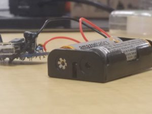
My Starter Project is the Minty Boost, and is able to charge a phone by utilizing two AA batteries. This charger additionally charges mp3 players, cameras, and other gadgets. The primary components of the charger include resistors, capacitors, a 5V boost converter, a Schottky Diode, a IC socket, and a 10uH power inductor. These components are soldered to a Printed Circuit Board (PCB).   I faced numerous challenges, for example learning how to solder properly in my circuit board which took me a good time in order to accomplish. Furthermore, I had to desolder because of some of the connectors, connecting with each other creating a false connection between the two parts of the board. One of the major attributes I learned from this scenario, was the key importance of patience. The project works by transferring the current from the charge in the battery into the phone. The diode forces the electric current to pass in one direction and blocks the current from moving in the opposite direction, compelling the current to move to the gadget from the battery and not vice versa. The IC socket protects the boost converter chip. The power inductor stores power and converts power to different voltages. As a result, energy from the 3V input from the AA batteries can be converted into a 5V input to charge the gadget. Lastly, the most important component is the 5V boost converter chip, which steps up a voltage from the input to the output. These are the technical aspects for the charger. Overall this project gave me a basic understanding of what hardships and journeys must be faced in the engineering world.

Leave a Comment

Start typing and press Enter to search

Bluestamp Engineering