My name is Ying Bin and I am a rising senior at Raoul Wallenberg High School. I looked into Bluestamp Engineering in order to conceptualize the countless equations for electricity and magnetism I memorized while studying physics. For my starter project, I built a light organ, a device that lights up according to the beat of the sound waves captured. As for my main project, I built an Infinite LED coffee table, a table that creates an optical illusion of a tunnel of LEDs at the center. I chose these projects because I was fascinated by breathtaking aesthetics produced by simple LED lights.
Main Project: Infinite Mirror LED Coffee Table

For my main project, I built an Infinite Mirror LED Coffee Table. My project consist of LEDs, balsa wood, a coffee table, TONS of wires, MOSFETs, an Arduino-MEGA 2560, and many other components. For the completed bill of materials that I used to make this project, refer to the file below.
Bill of Materials:LED Infinite Mirror Bill of Materials
The Code
Making the code for my project was probably the most educational part of this project. Prior to Bluestamp Engineering, I had messed around with Python without really knowing what I was doing. Making the code so that my table shows an alternating pattern has really taught me a new language. For my code, I had to set some values to each pin. This had never really caused me a problem. The next step was to set an output on each value in order for the LEDs to light up. I was tricked up by this a couple of times because I usually think it was a problem with my circuit being shorted whenever the LEDs don’t light up . It didn’t take too long for me to realize it was my code that was not functioning but it did waste a lot of time while I was rearranging wires. The last step of the code was to set the pattern. At first I was setting delays in between every line causing my pattern to mess up but with a little help from the instructors, I was able to get my pattern working. There were a couple other things that went wrong with my code, such as setting the wrong serial port, but I was able to figure it out and get my LEDs to light up as I have coded them to. Since I did not have time to create the pattern I had planned to make during the time of the program, I will be attempting to create a new pattern now that the program has ended. If you are making this project and would like to use the same pattern as I have, the code I used will be posted below.
Code: https://gist.github.com/Stringbeanwu/6030839
The Mechanics
The mechanical aspect of this project was by far the most time consuming. In order to mount the circuit I built, I needed to make a frame. Sounds easy right? Wrong. In order for the circuit to go to the solder board, I had to sand out about 35% of the wood that I cut. I started out by using sand paper but quickly moved on to using a drumel since using sand paper would’ve taken ages. The drumel sanded the wood relatively fast in the beginning, however, the process quickly decelerated as the drumel heads were worn down. Ordinarily, someone would use a drumel for about 5 minutes; as for me, I used it for about 4-5 hours. Nearing the end of my sanding session, I found a drumel head that would not wear out as easily as well as having a neater finish. If you are planning to make this project, I HIGHLY recommend using the cylinder drumel head. I was not finished sanding after this. In order to make my frame fit, I had to have each piece of wood perpendicular with the table. While this may sound easy, I probably spent about 3-4 hours doing this since I had to test whether or not it was perpendicular by letting it stand alone. After completing the frame, it came time to cut the table. On the bottom, I cut a 12.75″x 12.75″ square in order to fit my mirror and my frame(Note: when ordering mirrors, they may not come exactly to size. My 12″ x 12″ mirror came in as 11.75″ x 11.75″). On top, I cut a 12″x 12″ hole to fit my one way mirror. The top cut was shifted a little to the side and up so I could not fit my one way mirror. To accommodate this, I cut the hole to be slightly bigger and was left with a small gap on the top of my table. To keep everything in place, I epoxied the frame to the table as well as the bottom mirror edges to the frame. The top mirror was held up by the frame without epoxy and I decided to leave it like that so I can troubleshoot if anything goes wrong. You can look at a picture of the wood I sanded and a file to the mechanical design of my table below.

Mechanical Design: Final Mechanical Design(Note: I am using Google Sketchup in one of the files)
The Circuit
The circuitry of my project was the most tedious part of this project. Before I soldered anything, I built a replica of my circuit on breadboards. Although the circuit was relatively simple, there was an IMMENSE amount of wires. If anything was ever unplugged on the breadboard, I had to follow all the wires in order to find where I messed up. However, I learned from my mistakes and used color coded wires for the circuit on my table. There was still a lot of wires but debugging my circuit was much easier. For my power supply, I am using a 9 volt 650 milliamphere wall adapter. This adapter powers my Arduino but since the amount of power I was giving to the LEDs would be too much, I had to add a series of resistors before each LED in order to dissipate some power before it reaches the LEDs. Furthermore, I added a wire to the 5V pin on my Arduino before the current reaches the circuit so I get the appropriate voltage. Given that I wanted to control the LED patterns in my circuit, I had to add MOSFETs. Each MOSFET has 3 pins: a gate, a drain, and a source. The gate pins were connected to the Arduino and tells whether or not to give voltage to the MOSFET. The drain pins were connected to the LEDs. Since I had to connect six LEDs to each MOSFET, I had to short all of the LEDs to the drain pin. This led to some problems later since I did not check whether or not they were shorted using a multimeter. After I soldered all the drain pins, I had to solder all the source pins to ground. After I was all finished soldering, I started putting the LEDs into place and connecting the wires. This is where color coding the wires really helped. The next step was to start up the LEDs and debug. This is where I found out that some of the LEDs were not shorted to a MOSFET and since I did not have the time to take apart my circuit(this was on the second to last day), I resorted to soldering up-side-down. Although my circuit still has a couple of bugs, it works very well and I am very proud of it. If you want to build this project and use the same circuit as me, you can view a picture of my schematic and circuitry below.
Schematic:

Final Circuit:

Conclusion
I joined Bluestamp Engineering thinking that I would easily be able to finish any of the projects considering my participation in my school’s Maker Faire Club. I was terribly wrong. I had to use everything I learned in physics and apply it to my project in order to complete it. The new concepts that I was learning every day, ranging from soldering boards and wires to understanding how MOSFETs operate, were constantly overwhelming me, yet I could not believe how much fun I was having with the challenges that I faced. In spite of how much I grew in terms of knowledge and experience, my growth in character was not overshadowed. Throughout all the frustration, I learned that persistence is the key to success; most of the time it is usually just one shorted wire or one extra number in my code which I overlooked that was causing my project to fail. Furthermore, I learned to be more patient and self-sufficient by researching my components rather than relying on others to give me the answer. After six weeks of soldering, sawing, and coding, all my efforts paid off once I saw my LEDs light up as I have coded it to.
First Milestone: Finished Circuit Prototype
Hi, my name is Ying Bin and for my first milestone, I completed the prototype circuit and its corresponding code. In my code, I had an experimental section where I would test to see whether or not the LEDs were lighting up according to what I expected. To make sure this doesn’t show up in my display, I commented the experimental section. For my display, I had the LEDs alternate colors as if they were travelling from LED to LED. As for my circuit, the current travels through from the power supply to resistors, each of which are connected to the common anode of a LED. It then travels through the LED out of each cathode(Red, Green, and Blue) and into the gate pin of a MOSFET. The MOSFET is also connected to a ground and an arduino pin. Whether the LED emits light or not is determined by whether or not my MOSFET is on or not in my code. Each MOSFET is connected to 6 LEDs. To see the light display that I have set up, refer to the video below:

Light Organ
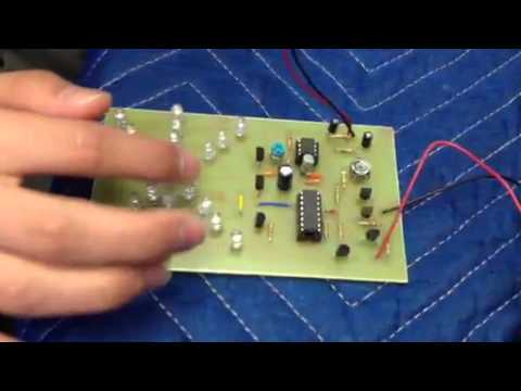
Hi, my name is Ying Bin and I decided to make a light organ for my starter project here at BlueStamp. A light organ is a device containing LEDs that lights up according to the frequency of the sound wave captured by the microphone. I chose to make a light organ for my starter project pursuing my love for music. Seeing lights flash up according to the beat of my favorite song is just a simply amazing sight. The main components of the light organ include: the mic, the transistors, the IC-555, the IC-4017, and the LEDs. The mic captures sound waves and converts them into electrical energy. Since the electrical energy is relatively weak, the transistors amplify the electrical energy and send them to IC-555. IC-555 creates wave pulses out of the electrical energy and sends it to IC-4017. IC-4017 counts the pulses and indicates which LEDs to light up. Other parts include a resistor, a potentiometer, and capacitors. Resistors impede current flow going into IC-555 and a potentiometer controls the resistance values of the resistors. Capacitors store charge as current runs through them.
After soldering countless LEDs, burning myself with the soldering iron, and desoldering an immense amount of solder from my circuit, I finally completed the light organ shown in the video below.