First Milestone—Changing the intensity of an LED
First Milestone
My First Milestone for the Magic Mirror is to have a working interface. The software focuses on a modular plugin system and uses Electron as an application manager. Electron uses Node.js and Chromium to build using Javascript, CSS, and HTML. It translates the code so it can be cross platform (Linux, MacOS, Windows, etc).
How to customize the modules
All the customization is done in the config.js file within the MagicMirror folder. However, if I wanted to use a third party module, I would have to clone the repository into the MagicMirror/modules folder first. In the config.js file, I can choose where to display the module (top_left, center, bottom_bar, etc), the header, and the configurations specific to the individual modules. The configurations can be found at the GitHub repository.
Most modules use an Application Programming Interface. An API is set of protocols and routines to build software applications. For example, I use Twitter’s API. There are two types: Rest API (Data Base) and Search API (Connects to my account). In order to use an API, I needed an API key. API keys are used to track and control how to the API is being used i.e to prevent malicious use of the API. It also acts as unique identifier and as a secret token for authentication.
Every single module on my MagicMirror uses an API because I wanted a customized interface that suited my personal needs.
Starter Project
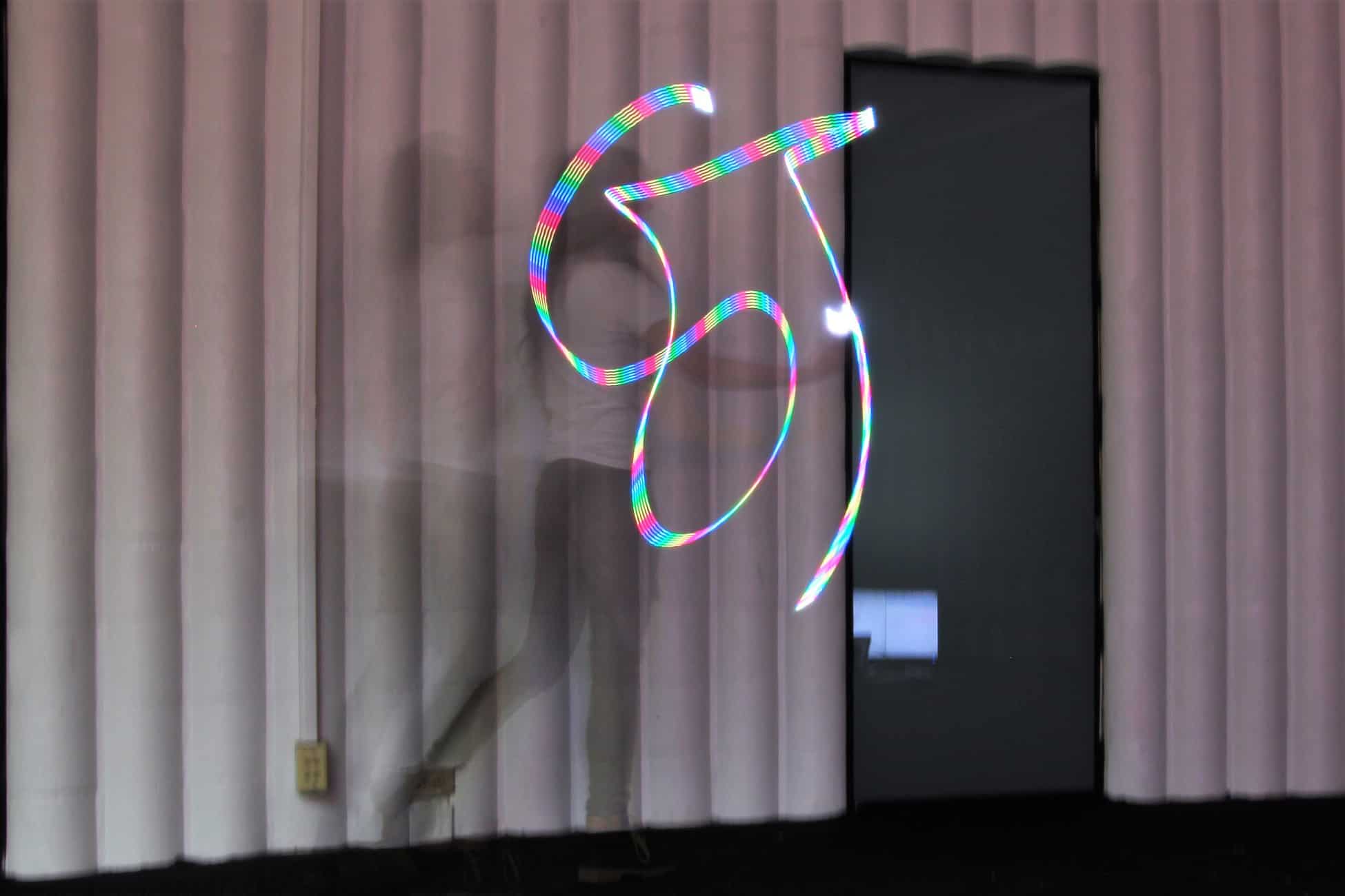
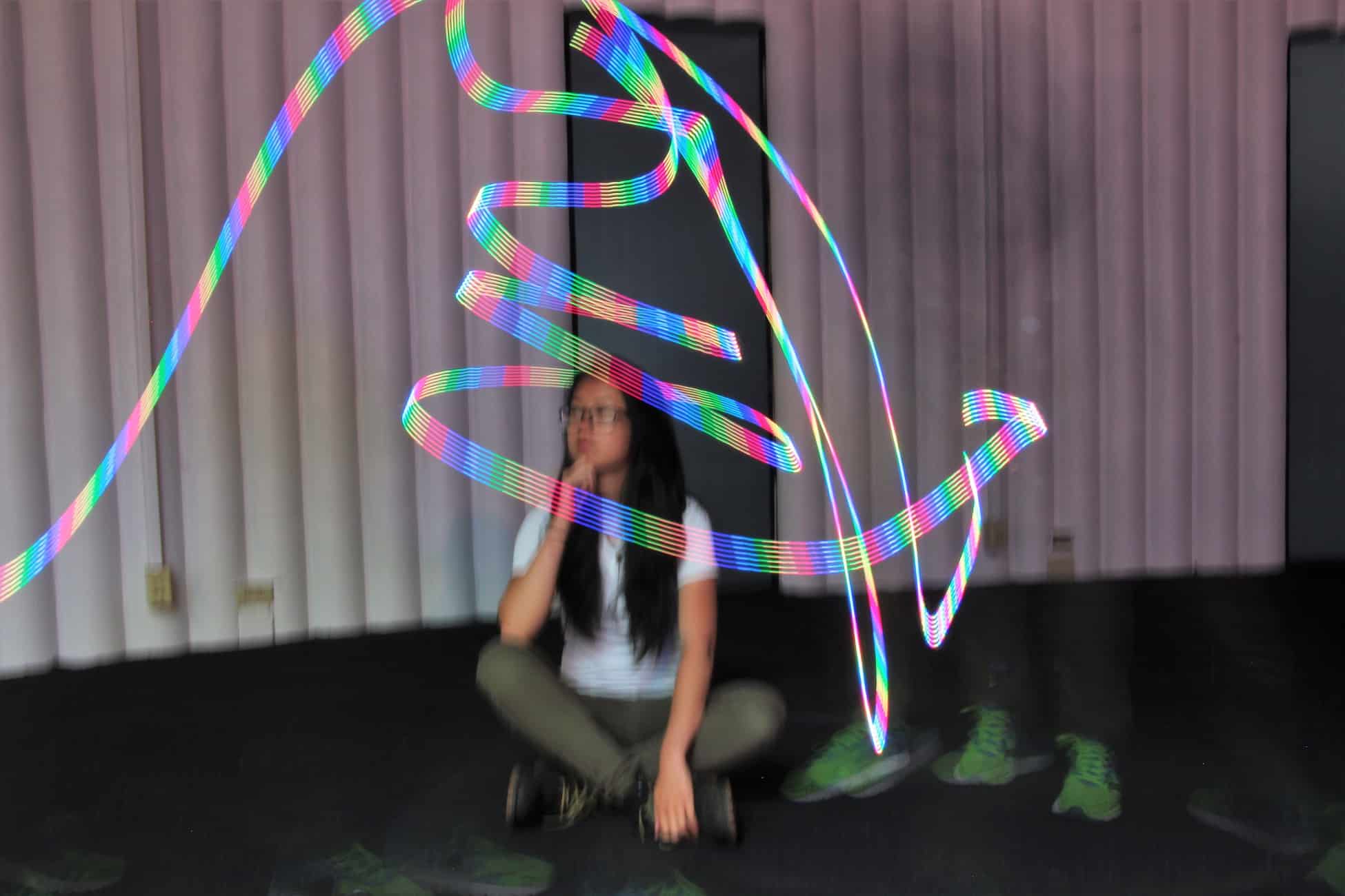
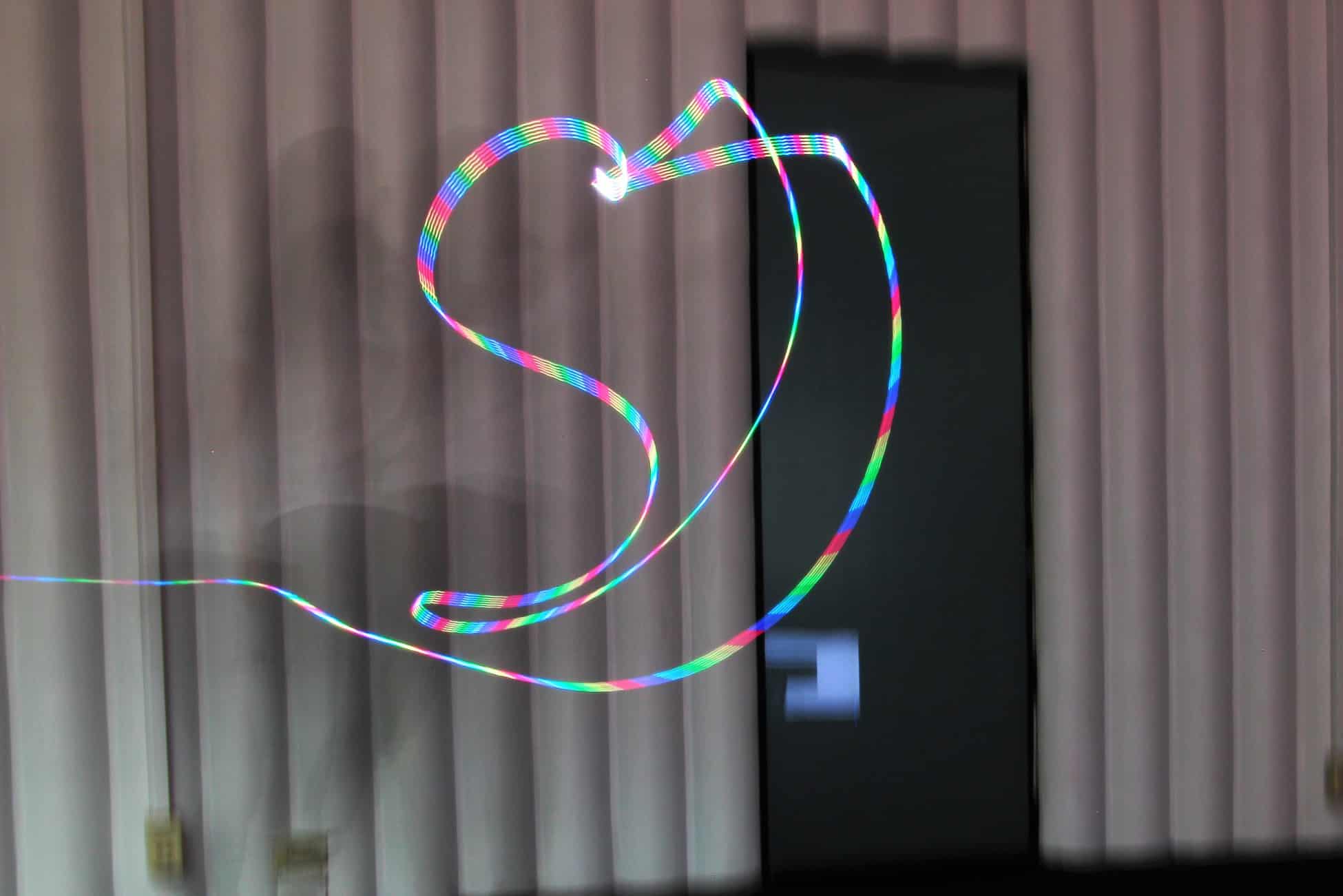
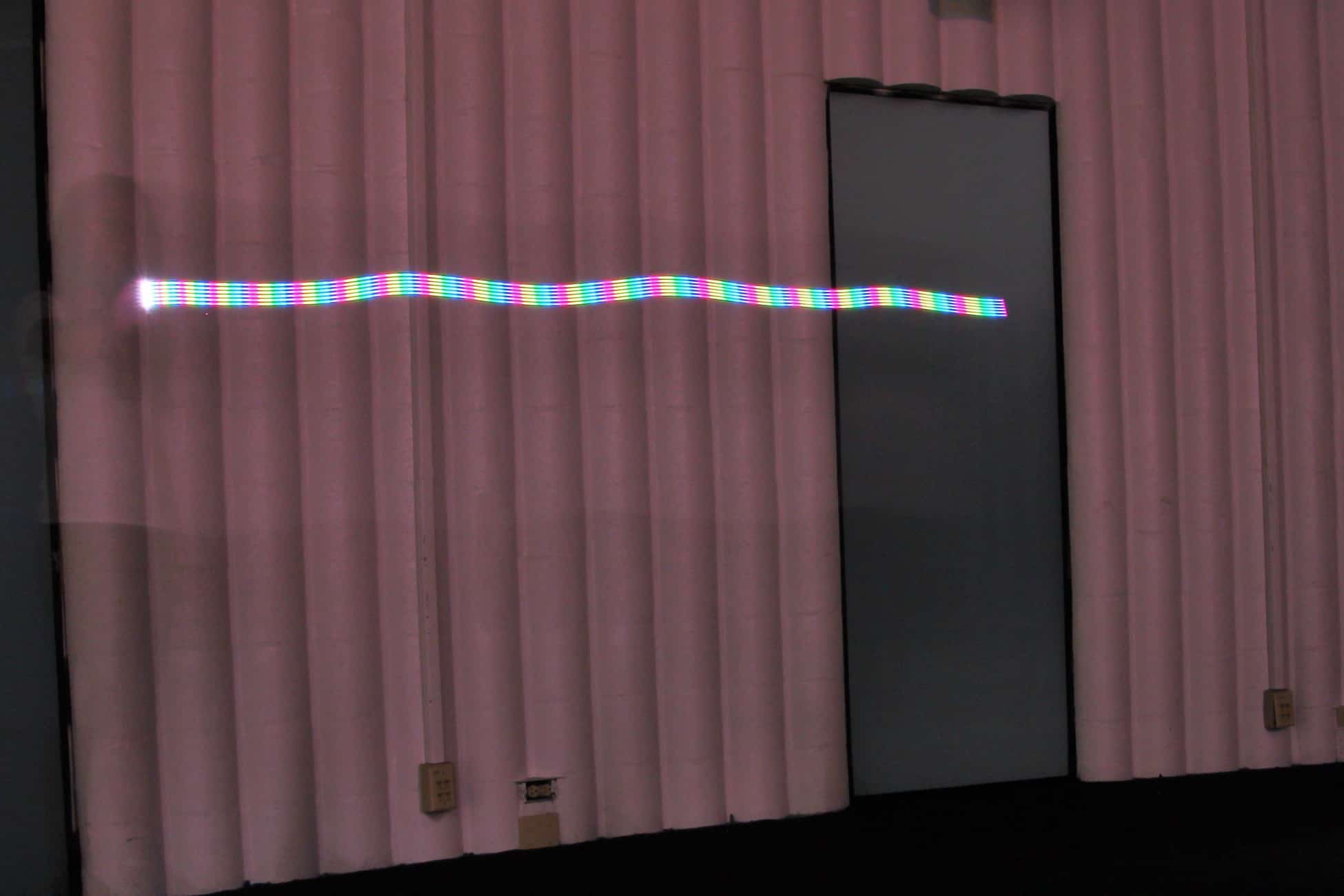
My Starter Project is the Mini POV 4, a fully customizable light painting kit. When you wave the POV in front of a camera on long exposure, it displays an image that appears to be floating. I enjoyed this project because I learned about the different electrical components and their roles in this circuit as well as how to solder.
Demonstration
How it works
The Mini POV 4 is powered by a 4.5V source. The 100μF and 0.1μ F capacitors work together to stabilize the current and filter out noise. The potentiometer, also known as a variable resistor, controls the amount of current that flows to the microcontroller. When the dial is turned, the input to the micro controller changes, which changes the output (the LEDs’ blinking speed). The 2.2k resistors limit current flowing to the 3 transistors. Because the micro controller’s signal is not strong enough to communicate with the LEDs, the transistors amplify the signal. Each LED has it’s own 47 ohm resistor that prevents the LED from overheating. In between the resistors is a ceramic resonator which acts as the board’s metronome and makes sure that the LEDs blink at a consistent rate. The board also has two diodes to make sure electrostatic discharge does not occur. Electrostatic discharge is when static electricity is released when two objects come into contact. The diodes also ensure that the data being transferred from a computer to the POV does not get interrupted. Last of all, there is the USB type B port that allows the user to customize the image on a computer by using the Mini POV 4 software. Users are able to draw their own 8 pixel tall image and download it to their POV.


