Introduction
Hi, my name is Vincent. I am a rising sophomore at Lynbrook High School. My two projects were the MintyBoost phone charger and a remote controlled car with a robotic arm controlled by a PS2 controller. I learned more about Arduino and how to code in Arduino. I also learned how to wirelessly communicate the PS2 controller to Arduino.
Code: Arduino Code
Bill of Materials: BOM
3d printed parts: 3d parts
Schematic: Schematic
Drawing and Assembly: Design
Final Project/Milestone 3
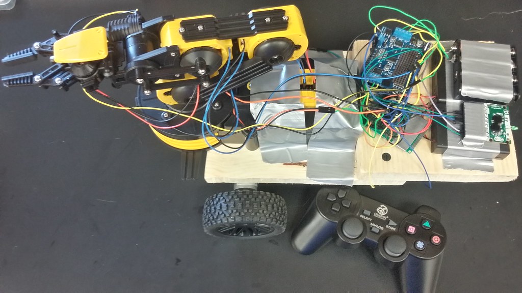
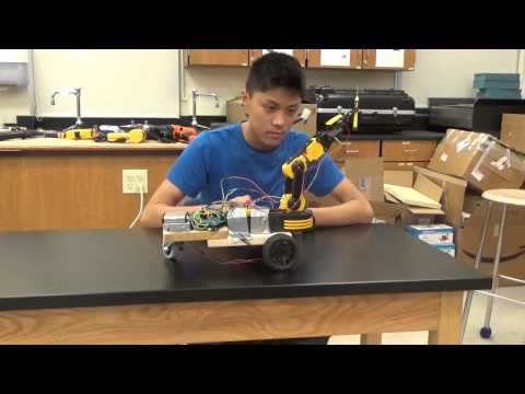
I made a remote control car with a robotic arm controlled by a wireless PS2 controller. I connected the wireless transmitter of the PS2 controller to the Arduino and programmed the Arduino to communicate with the PS2 controller through the transmitter. I also connected a motor shield to the Arduino to control the arm. I had to program the motor shield so it can control the arm wirelessly.
My third milestone is assembling the robotic arm, programming it to be able to be controlled by my PS2 controller, and mounting the arm onto my car. Assembling the arm was easy, but getting it to work with the PS2 controller was difficult. I had to use a motor shield, which I had not used before. A motor shield allows the Arduino to be able to control more motors at once. With the motor shield, I was able to add four motors for a total of six motors I could control for my car and arm. I also did not know how to program the motor shield, so I had trouble with that too. It was troubling because I couldn’t control my motors without the code. I looked at the code even more to figure out how to control the arm with the motor shield. I finally understood the different functions to make the arm move. I put those functions into the wireless PS2 code, and it worked. However, when I tested the arm and the wheels of the car, one wheel didn’t work. I found that the pin number variables of the arm were interfering with the wheels. I solved this problem by switching the pins of the motors on the Arduino. I also had to deal with the fact that I could only control four motors on the arm because there are only four motor ports on the motor shield. The arm was heavy, and was a little too big for my car. I solved this problem by doing my best to fit the arm onto the car. The weight did not affect the speed of the car too much.
Milestone 2
My second milestone is assembling the car, connecting the wireless PS2 controller to the Arduino and control the car, and fixing all the components to the base of the car. A few problems I had with the car assembly was putting on the motor mounts and the part to connect the motor to the wheels. The holes I drilled for the motor mounts were a little bit off, so I had to straighten out the motor mounts while I was screwing them to the wood. For the part to connect the motor to the wheels, the hole for the motor shaft was too small to fit. I had to drill a larger hole in the part in order for it to be able to connect to the shaft. The hexagon part of the part was small, so I put some epoxy on to secure it to the wheel. The second step after assembling the car was connecting the PS2 controller to the Arduino. I connected 6 wires from the wireless receiver of the controller to the Arduino so the Arduino can receive commands from the PS2 controller. A few problems I had with the controller were getting the wireless to work and the code to test it, understanding the functions, and getting the controller to be able to control the motors. I had to look at the wireless receiver closely in order to figure out how to connect it to the Arduino. After I connected the wires, I found the code to test the connection. I had to read the library of the functions in order to understand how to use the functions included in the library. I couldn’t figure out the functions at first, so I couldn’t figure out how to control the motors with the controller. However, I later figured it out, so I knew where to put the code for my motors. The first time I tested the code, the controls were not in line with the car, so when I wanted the car to move forward, it went right. I went back to fix the code and it worked. I then proceeded to put all the wires and H-Bridge onto a perf board.
Milestone 1
My first milestone is making a circuit for the H-Bridge and using the H-Bridge to control the motors. I connected the H-Bridge to a breadboard and connected wires from it to an Arduino. The H-Bridge has 4 pins for one motor, 2 inputs from the driver, and 2 outputs from the driver, 1 input and output for each pin on the motor. A few problems I had with running the motors was getting the motors to run, the code, and burning an Arduino. For my first problem, my circuit was wrong, so I had to fix the circuit in order to get the motors to run. For my second problem, I had to look at my code to see what I was doing wrong. I figured out how to set the pinMode of the pins of the Arduino to make the motors run. For my third problem, I learned to not put to much voltage into the 5 volts pin on the Arduino to avoid burning another Arduino. The design of my car is two wooden boards of similar sizes attached to each other. One board is attached on top of the other. The battery is going to be attached to the top with the caster wheel in front. The breadboard and Arduino are on the bottom board, with the motors attached to the underside of the bottom board. The robot will be slightly tilted, but that will not affect the performance of the robot greatly.
MintyBoost Starter Project
My starter project was the MintyBoost phone charger. It is a small and portable phone charger that uses a USB port and two AA batteries to charge any device. The parts of this charger included resistors, bypass capacitors, power capacitors, an integrated circuit, a diode, a power inductor, and a USB port all soldered on to the printed circuit board. The printed circuit board is connected to a two AA battery holder which supplies the power. The MintyBoost uses a boost converter and a power inductor to boost the voltage of the two AA batteries from 3 volts to 5 volts. Because the input voltage is less than the output voltage, a boost converter is used. If the input voltage was greater than the output voltage, then a simpler linear regulator can be used. The MintyBoost’s boost converter uses the inductor’s tendency to resist changes in current in order to increase the output voltage. The switch in the integrated circuit rapidly turns on and off fast enough for the inductor to not discharge in between turning the switch on and off. Therefore, the circuit will always have a higher voltage. This is the basic explanation of how the MintyBoost Works. Some problems I had with this project was learning how the boost converter worked and how it interacted with the inductor. I also had some problems soldering the components into the printed circuit board.