Incoming Senior

3D Robotic Hand

My main project is a 3D robotic hand that mimics the movements of a glove that the user controls. The glove has flex senors that send information to an Arduino that controls the hand.

Engineer

Victor Z.

Area of Interest

Software Engineer

School

George Washington H.S.

Grade

Reflection

My time at BlueStamp was a great introduction and dive into engineering. I was inexperienced and had no prior knowledge of the applications of computer science and engineering. I had taken a computer science class before this and what I can apply from that class to something physical that I can actually touch was exciting. I have learned how to solder, code, and much more through Bluestamp, but I believe that I haven’t even finished the basics. There is still a range of things that I have yet to learn. The great learning experience I had was all thanks to the amazing staff at Bluestamp. Without them, I’ll probably be still connecting the wires for my 3D printed hand.

Demo Night

Final Milestone
breadboard_picture
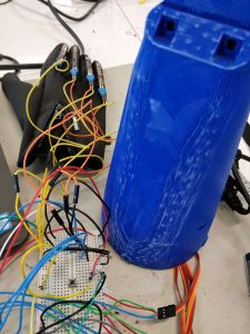
For my final milestone, I connected the servos into the robotic hand. I crimped the top of the fishing lines and ran it down to the servos. There were two fishing lines for each finger, one for pulling it down and one for pulling it back straight. This was one of the most difficult and most annoying part of the project. The wires get tangled easily and I often mistake one for another. You had to correctly attach the fishing lines to the servo horns so that both fishing lines have enough tension to complete its duty. Another problem that I came across was that the crimp tubes at the top of the fingers would sometimes let loose when the servo pulled down. I had to rewire those lines again because of this. After a long time, I had finally connected everything. The next step was sewing the flex sensors onto the glove. This was relatively easy and only took me half an hour. When I tried testing it out, the servos all worked except for the one that was connected to the middle finger. It had previous made weird sounds and had not stopped working. I had to remove both the fishing line and the horn.
37323945_2118432105083900_2317795276133236736_n-1

Milestone 2

schematic
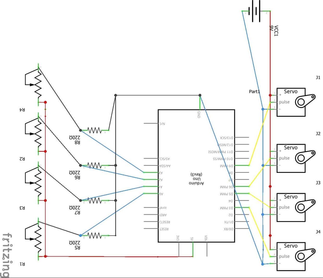
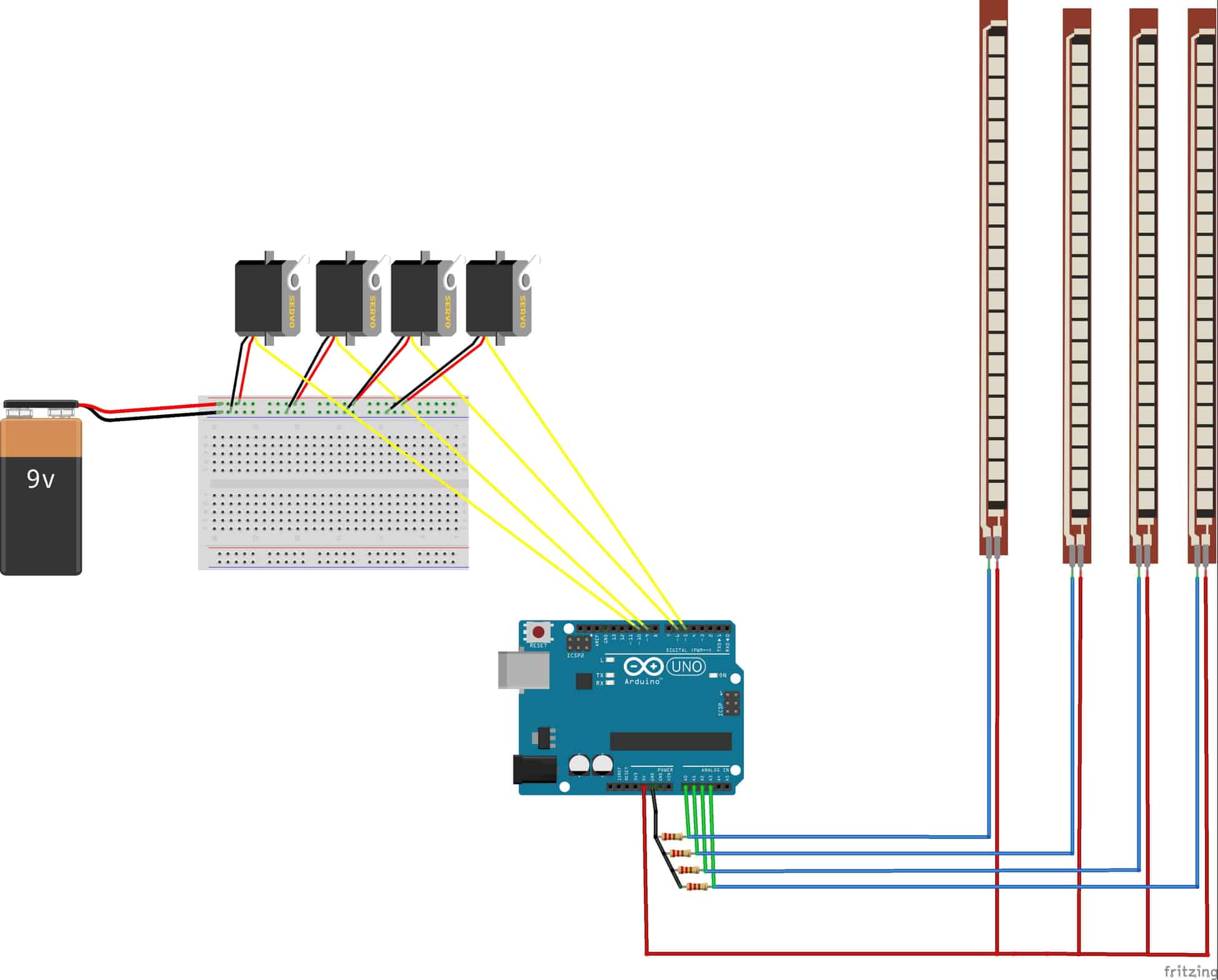
For my second milestone, I connected the flex sensors to the servos. The code I’ve written for it receives data and information from the flex sensors and moves the servos according to the information received. The flex sensors are like variable resistors. Bending them changes the amount of curr?ent that goes through it and it sends that information out.There are four resistors for each flex sensor. All four of the resistors are powered by the arduino itself. Both the flex sensors and the servos are connected to the same breadboard. The wiring is very confusing right now but I will later transfer everything to two seperate PCB boards. The most difficult thing about this first milestone was the code. I have only programmed in java before and programming for the arduino was strange. Fortunately, a lot of concepts from java were also in the language for arduino.     

Milestone 1

servo_picture
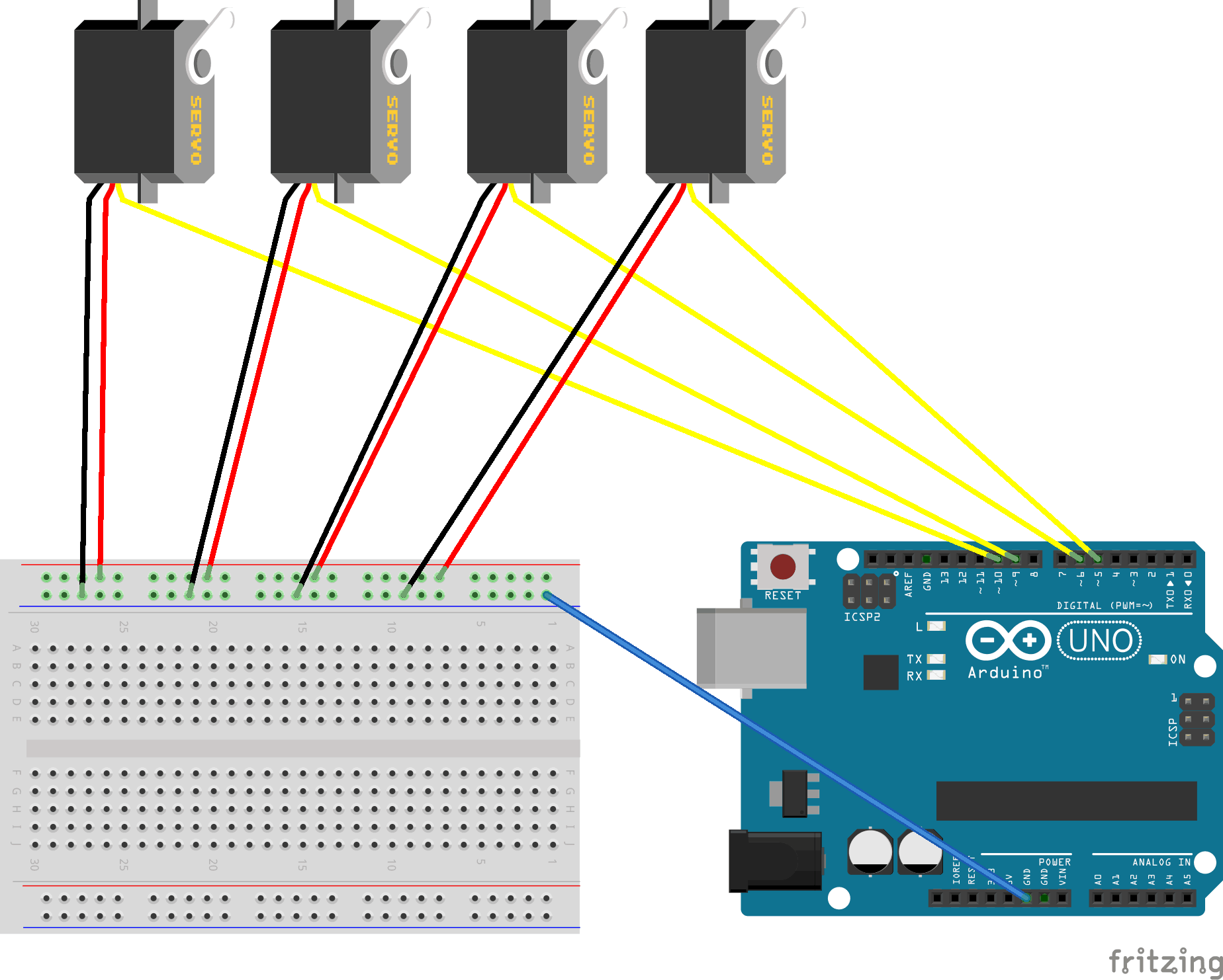
My first milestone was connecting the servos to the arduino. I temporarily connected the servos to the breadboard. Using the breadboard is more of a prototype because the wires currently are a bit wobbly and can disconnect easily. The positive and negative wires are each connected to the breadboard, either in the positive or negative power supply. Additionally, each servo has a signal wire that receives instructions from the arduino. All four of the servos are powered by one 7.4V battery. A ground wire is connected from the negative power supply on the breadboard to a ground pin on the arduino. I wrote a code for just testing out the servos. The code turns the servos right once and left twice. The code is looped so it is repeated over and over again. I can’t move the servos to specific angles because I haven’t connected the flex sensors to the arduino yet. A problem that I first encountered was with wires. I used random wires lengths and ones with different colors at first. This was a problem because it easily confused me and tangled because they were different lengths.This was dangerous until new wires were available and I could finally color code them.        

Starter Project

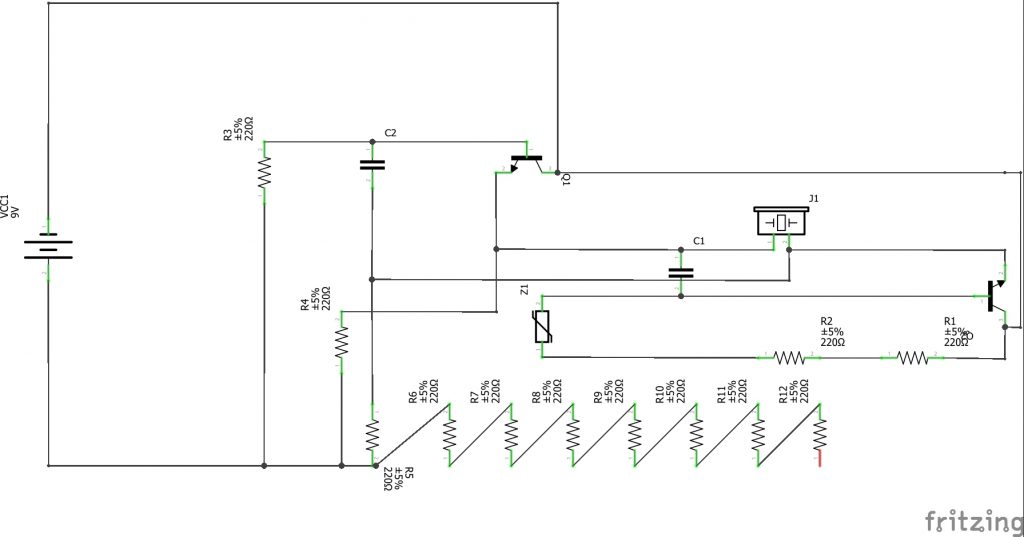
My starter project is the electronic bagpipe. I started soldering the resistors in, which are located near the keyboard. I then soldered the capacitor and the transistor in the board. Capacitors is almost like a battery. Both batteries and capacitors hold energy, but capacitors, unlike batteries, don’t produce energy. Transistors stop and start a current. It can also amplify the current. The PIEZO is the last piece that I put in. These connect to the variable resistor, which lets you control the resistance. This allows me to control the pitch of the noise that comes out of the speaker. The speaker is a PIEZO that can turn electrical signals into sound. A problem that I first encountered was that one of the keys of the keyboard didn’t work. The top half of the resistor worked when it was touched with the stylus, the bottom half didn’t. I proceeded to check the back of the bagpipe to look for any problems. I didn’t see any problems with the soldering and just decided in the end to clip off any ends that might be touching other parts it wasn’t suppose touch. This solved the problem.

Leave a Comment

Start typing and press Enter to search

Bluestamp Engineering