
Musical Lock Box
My main project is a musical locked box which opens after detecting a specific sequence of musical notes. Each time a correct note is played, an LED turns on and lights up. When all the LEDs are turned on, the servo will turn, unlocking the box.
Engineer
Huishan L.
(Vanessa)
Area of Interest
Computer Science
School
Galileo Academy of Science and Technology
Grade
Incoming Senior
Final Product
Songs Used in Code:
Final Product
Includes:
- All Milestones
- Two Sets of Melodies
- LED Lights
The songs used in this project are for personal use only.
“Copyright Disclaimer Under Section 107 of the Copyright Act 1976, allowance is made for “fair use” for purposes such as criticism, comment, news reporting, teaching, scholarship, and research. Fair use is a use permitted by copyright statute that might otherwise be infringing. Non-profit, educational or personal use tips the balance in favor of fair use.”
HANN (Alone): ℗ 2018 CUBE ENTERTAINMENT
XianYun:
Final Milestone
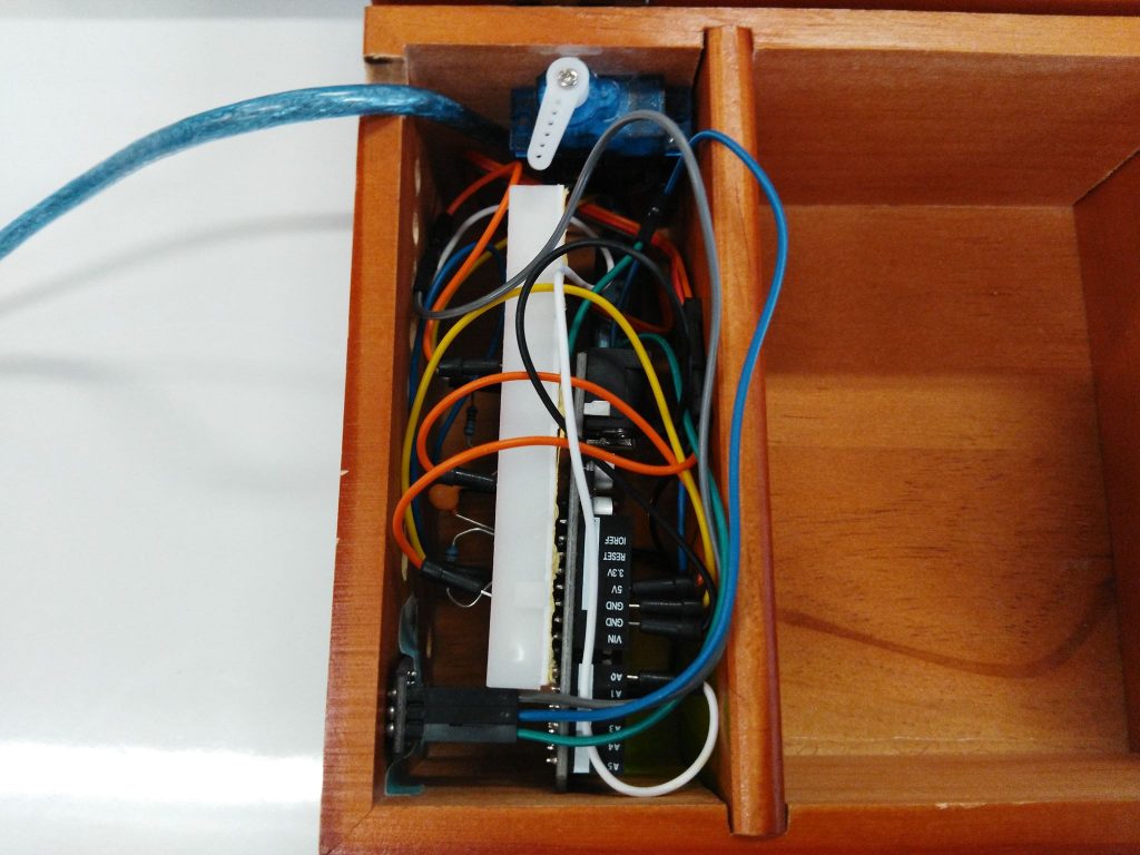
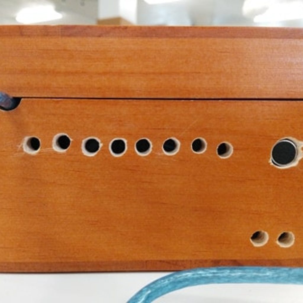
My final milestone included drilling holes in the box for items that can be seen from the outside and placing all my components inside the box. Just a note that although this is my final milestone, it is not my final product, as I planned for the project with modifications to be my final product.
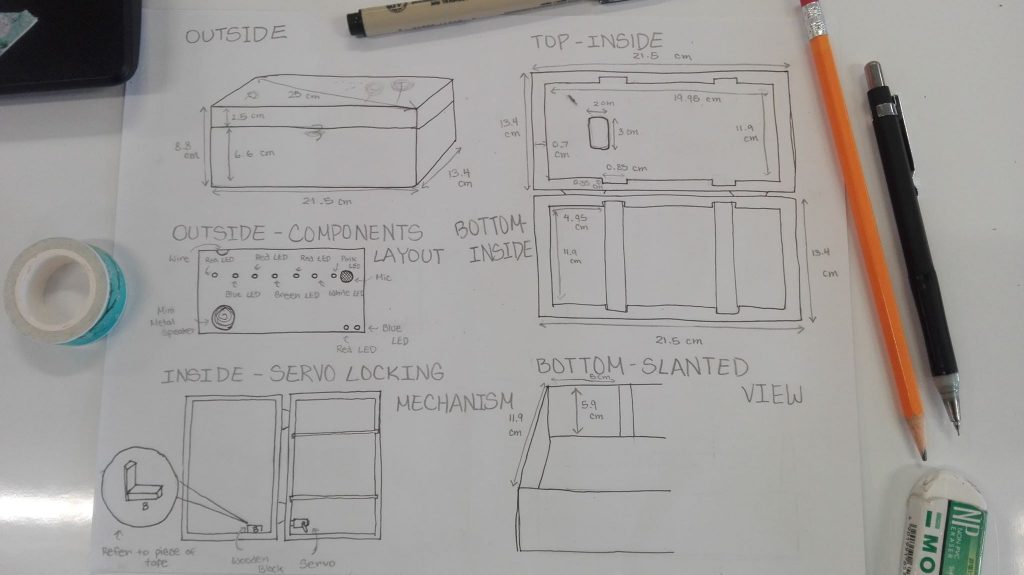
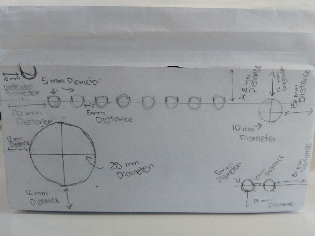
Prior to drilling holes in my box, I made a detailed plan of the measurements of the box and the placement of where I wanted parts to be, the size of parts, and their distance from various locations such as another part or the side of the box.
While this plan did help me a lot when drilling, I still made an error when gluing the servo in place. I accidentally glued it at a point where the box could be opened to quite a degree even when locked. I originally planned to attach a piece of wood to the servo so that it would lock properly. However, to save time, I removed the servo from the side of the box using a flat screwdriver and reglued it in a proper location.
This was my first time using power tools like the drill, so it was expected that not all the holes were perfect and had bits of wood slightly damaged. In addition, my filing/sanding may have scratched the surface of some parts and made some holes slightly larger than they needed to be. As a perfectionist, this was not a fun experience since I was not satisfied with how things turned out afterward, but for something that was done by a first-timer, it looks decent enough.
I also had trouble with the microphone. Prior to placing everything inside of the box, the microphone was picking up sound properly. In fact, it was even better than when I did testing in earlier stages. After confirming everything was still working properly, I placed everything inside the box. However, once everything was inside and in place, the microphone stopped working as well. After some tinkering, I found that if I changed the orientation to upright instead of sideways, the chances of it hearing the correct frequency increases. In addition, I pushed the microphone in as much as possible so that it would be touchable on the outside and not slightly inside the hole. This way, I can place my phone’s microphone directly on the project’s microphone and sound can be picked up easier.
With the microphone and locking mechanism in place, the essence of the box is there, thus making my musical lock box “complete”. As stated earlier, although this is the final milestone, it is nowhere near the final product I wanted so my next step will be to add in my modifications. This includes modifying the code so that two different sets of melodies can be used to unlock the box, adding LEDs to help me determine whether a note has been heard or not, an MP3 player that plays the full song after unlocking, and designing visuals for my box, as I have already planned for it to follow a certain theme since the very beginning.
Second Milestone
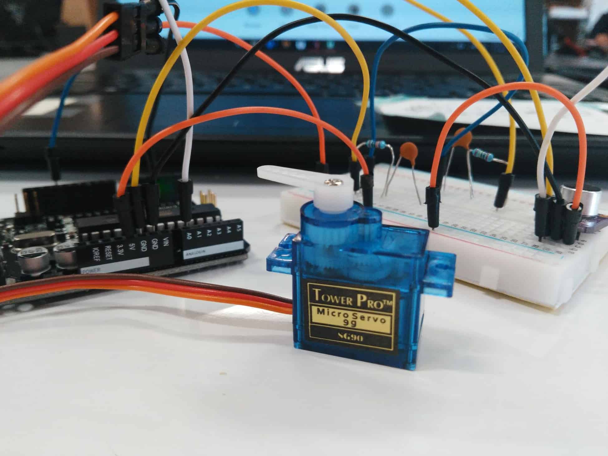
My second milestone was to get the servo to turn after hearing the notes being played in order. To do this, I used cornelam’s “Arduino Servo Motors” instructable to help me wire the servo to the Arduino and write the code. Using the code in step 2 as a reference, I added the servo library, declared the servo pin and created the servo object. Then I attached the servo to the pin and set the servo to 105 degrees in setup. Finally, I programmed the servo to go to 180 degrees after hearing the last note.
Since I needed the servo to unlock only after hearing all the notes in a specific order, I created a bool variable for each of the notes. Initially, they are all set to false. When the first note is heard and registered by the Arduino microcontroller, it sets the first bool variable “n1” to true. Then, it looks for the second note. Once the second note is heard, it prints the note name on the serial monitor and checks if the first note was registered before setting the second bool variable “n2” to true. If the first note was never registered and “n1” is still false, then “n2” will also be false even if the note was heard. This continues until all 7 notes are heard and their bool variables are set to true. When the final bool variable “n7” is set to true, the servo will turn to 180 degrees and unlock.
While testing my code prior to the addition of the bool variables, I ran into a problem. In setup, I wrote “HANN.write(0);” to get the servo to start at the position 0 degrees. Since it was in setup, the servo was expected to only move once. However, it continued trying to move even after reaching its limit. I found out this was because the Arduino is not able to control the servo in a way that would get it to reach exactly 0 degrees. To solve this, I made adjustments to the code and changed the rotation of the servo. For now, the values are not the actual ones I’m going to use, but it will be changed later.
Another problem I faced was getting the servo to unlock after hearing the second C#7 and not the first. Since they were consecutive notes, I did not have a note in between to separate this. I got some help from my instructor April and set it so it would check if “n6” is true before checking “n5” which is the proper note that needs to be heard next in the sequence. This way, it would be able to recognize two C#7 notes and unlock only after the second is heard.
I also added code that prints the values of “n1” – ”n7” in the serial monitor as a way to check if the note has actually been registered and that its bool value has been changed to true. In addition to this, I added code that will relock the box when the note “A5” has been heard.
First Milestone
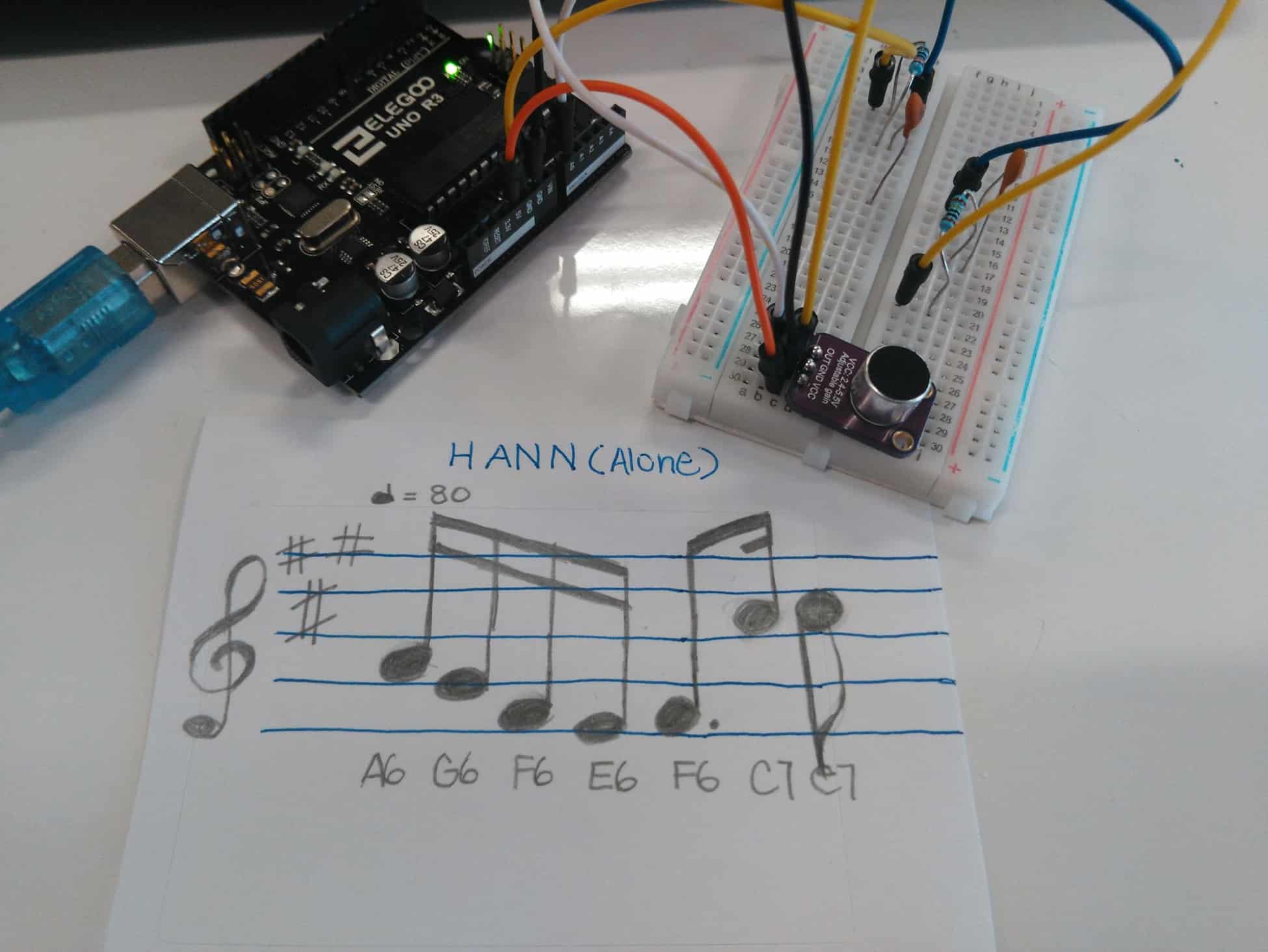
My first milestone is to program code that’ll get the microcontroller on the Arduino to recognize the notes I wanted it to. When the frequencies of notes in a specific range are detected by the microphone, it will send this data to the Arduino. This data is then printed on the serial monitor as either “frequency” Hz or the name of the note if it was one of the notes I wanted. The code I used is from Amanda Ghassaei’s “Arduino Frequency Detection” Instructable with additional reference from former BlueStamp student Katie’s Milestone 1 code.
Different notes have different frequencies. The higher the note is on the chromatic scale, the higher its frequency. In addition, the higher the octave of a musical note, the higher its frequency. For example, although A4 and A5 are the same note (A), their frequencies are different because they are one octave apart. A4 has a frequency of 440 Hertz (the unit of measurement for frequency; Hz) while A5 has a frequency of 880 Hz, twice the frequency of A4. This is because the formula for frequency is wave speed/wavelength. Shorter wavelengths equate to a higher frequency while longer wavelengths equate to a lower frequency. This is why A5’s frequency is higher than A4’s despite being the same note.
The code I used for this milestone calculates the frequency of sound using the slope and period of the sound emitted by my phone. As explained above, notes with a higher frequency have shorter wavelengths. A shorter wavelength means that the slope and period of a wave are higher. Using this code, notes of different pitches were differentiated from each other based on their slope and period, allowing me to be able to accurate program the ATMega328 microcontroller to recognize the notes I needed.
While working on this milestone, I faced a lot of challenges. For the first two days, I couldn’t get the Arduino Nan with an ATMega328P processor to read the frequencies. Even when I used Katie’s accurate milestone 1 code, it would still display “0 Hz” on the serial monitor. At best, it would display frequencies up to 60 Hz but never anything above it. I tried switching to using an Arduino Uno R3 instead, but the same problem still occurred. Later on, I changed my microphone and paired it with the Arduino Uno R3. Afterward, the sound started to be picked up better. This was the combination I stayed with.
In addition to changing microphones and Arduino, I also installed a high and low pass filter that filter out sounds below and above a certain range. While trying to figure out why the microphone wasn’t picking up frequencies accurately, I used an oscilloscope to check on the waves of the sound that was picked up. I found that the waves were distorted, possibly due to interfering sound from the surroundings that was picked up by the mic along with the sound coming from my phone. To counter this, I added the two filters that wouldn’t allow sound below and above a certain range to be picked up.
My next step is to work on programming the servo which would unlock the box after the programmed sequence of notes are played.
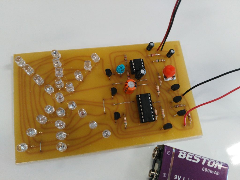
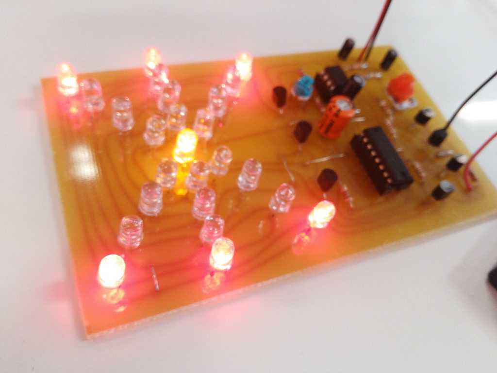
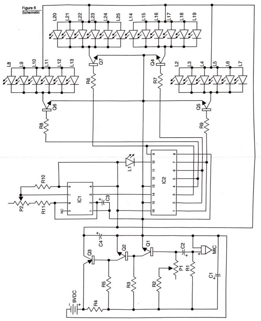
A 9-volt battery is connected to the circuit, producing the current which is used to power the circuit. (To prevent various parts from receiving too much current from the battery and burning, resistors were installed to control the current flow.) The current is stored by capacitors and only released when sound is picked up by the microphone. The sound is amplified by transistors to the level needed to turn on the ICs. When IC1 is turned on, it sends a pulse– which is a short burst of sound, electrical current, light, or any other wave– to IC2. Each time IC2 receives a pulse, it outputs it to one of the output transistors (Q4 to Q7) in a specific sequence. These output transistors are what’s responsible for turning on the LEDs.
When building this project, I didn’t run into any problems since the project mainly consisted of soldering. My only concern throughout was trying not to burn myself (hair included). My main takeaways from working on this project were learning how to solder and how different electrical components work.