Smart Garden

           My name is Valentina, and I am a rising sophomore at Loyola School. My project is the Smart Garden. The Smart Garden is a monitoring and automatic watering system. The system monitors how much water my plant has, displays the data on a graph, and pumps water in the plant as necessary.

Engineer

Valentina

Area of Interest

Mechanical Engineering; Electrical Engineering

School

Loyola School

Grade

Rising Sophomore

Reflection:

            BlueStamp gave me the opportunity to learn about soldering, programming, and the functions of all the parts of my project. I can use what I learned in future projects. This experience also gave me an idea of what working in an engineering field would be like, which is something I would like to pursue.

Final Milestone

             My project is the Smart Garden Monitoring System, which is a monitoring and automatic watering system. The system uses two sensors to receive its data: a water level sensor in the water container, which detects the amount of water in the container, and a soil moisture sensor, which detects the amount of water in proportion to the amount of soil. The Arduino uno receives the data and the Raspberry Pi takes that data and displays the changes in the amounts of water on a graph. BlueStamp gave me the opportunity to learn about soldering, programming, and the functions of all the parts of my project. I can use what I learned in future projects. This experience also gave me an idea of what working in an engineering field would be like, which I am very interested in.  The Smart Garden code and water level and soil moisture graph are attached below.

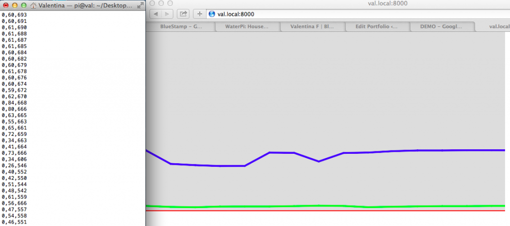
Water Level & Soil Moisture Graph:

screen-shot-2018-08-01-at-12.21.38-am
Click Here for Smart Garden Code

int sensor_pin = A1;
int output_value ;
void setup()
{
Serial.begin(9600);
Serial.println("Reading From the Sensor ...");
delay(2000);
}
void loop()
{
output_value= analogRead(sensor_pin);
Serial.println(sensor_pin);
output_value = map(output_value,0,1023,0,100);
delay(500);
int sensorValue = analogRead(A0);
Serial.print("Mositure : ");
Serial.print("0");
Serial.print(",");
Serial.print(output_value);
Serial.println("%");
Serial.print(",");
Serial.println(sensorValue);
delay(500);
}

Second Milestone

         I am working on my main project called the Smart Garden, which is an automatic watering system for my garden. The system monitors the water level of my water source and the moisture level of the soil of my plant using water level and soil moisture sensors, displays the data on a graph showing the changes the sensors detect, displays some of the data such as temperature or humidity on the LCD screen, and pumps water from the water source to the plant, depending on if the plant needs it or not. For my second milestone I tested the water level sensor and soil moisture sensor and set up the raspberry pi. Using the raspberry pi I was able to display the data the sensors detected on a graph. A challenge I faced was my overall lack of experience with raspberry pi. I learned how to use it and how to display the graph of the changes in water level and soil moisture level. In the image below to the left, the blue line represents the water level change after I lifted the sensor out of the container; the green line represents the soil moisture level; and the red line represents the value of zero (no water).

Water Level & Soil Moisture Graph:

screen-shot-2018-08-01-at-12.21.38-am

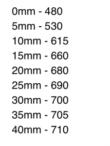
Water Level Conversions:

image-1

First Milestone

            I am working on my main project called the Smart Garden, which monitors the moisture level of the soil of a plant, displays the data on a LCD screen and on a graph, and pumps water into the plant by processing the moisture level of the soil. For my first milestone I assembled the base of the whole project. I attached the arduino uno to the water level sensor and soil moisture sensor which is essential to receiving data from the plant. Without the arduino circuit, the raspberry pi would not be able to use the data to determine the amount of water to give to the plant.

Starter Project

       Many board games require dice to carry out the play. I assembled an electronic die. Unlike typical dice, the electronic die is only one-sided and has seven LEDs that light up in different patterns and random numbers, 1 to 6 LEDs light up. Everyday dice are rolled while the electronic die displays its lights in response to being tapped on a flat surface. The electronic die’s LEDs light up randomly because the die “reads” the impact against a flat surface using the piezoelectric sensor, which generates an electric charge in response to applied mechanical stress, attached to the bottom of the die. The LEDs are all connected through resistors to the PIC microcontroller, which receives the signals (caused by impact) and generates the associated number of lights on the face of the die. I soldered the hardware to the main dice kit, glued the piezoelectric sensor to the acrylic bottom, and screwed the acrylic bottom to the dice kit. The first challenge I came across was my overall inexperience with a majority of the soldering. I had never been involved with anything I encountered. Today I learned how to solder. The second challenge I came across was my first attempt at creating an impact that would light the electronic die. None of the LEDs lit up and I discovered it was because I had not taken off the rubber outside of the piezoelectric sensor’s red and black wires. After I resoldered the red and black wires the LEDs lit up as previously expected. I really enjoyed my first day at BlueStamp. I learned some things I had only had a glimpse of before this program and I gained some knowledge and experience with some tools. I really enjoyed the outcome of today’s project (the electronic die), and I am glad to have finished it. I really enjoyed learning about how all the parts work and how the whole build functions.
Comments
  • Brenda Obando
    Reply

    I never have to fetch my die from under the table again (from rolling it too hard). This is really, really clever!

Leave a Comment

Start typing and press Enter to search

Bluestamp Engineering