
Introduction:
Hi! My name is Tristan and I am a rising high school Junior in Houston. This summer at BlueStamp Engineering I will be working on a self-balancing robot, commonly known as a Segway. I chose this project because I wanted to do something interesting, yet challenging, and complete the building process from start to finish. This began with the construction of a Bill of Materials and the creation of a Build Plan that organized my project into scheduled milestones (seen below).
Completed Project Photo:
The Process:
One of the things I enjoyed most about BlueStamp was that for the first time I was able to take a project all the way from start to finish. Upon arrival, I was given a box that contained the things necessary to build my formerly hypothetical self-balancing robot. At first this appeared to be quite a daunting task, but gradually began to seem possible as I approached its realization.
Now for the nitty gritty details.
The Sparkfun USB Host Shield (with a Bluetooth Dongle) sits connected on top of the Arduino Mega 2650 that sits on the bottom level of the robot next to the Pololu VNH2SP30 Dual Motor Driver Carrier. The Arduino uses PWM (Pulse Width Modulation) to control two 12 volt DC motors located underneath the robot. PWM works by sending variable digital pulses that serve to dictate the speed that the motors turn. Rachel (my Lead Instructor) analogized PWM as the the optical illusion of regularly flashing lights appearing as a continuous dim glow. But, you may ask, how does one determine the correct rate at which to apply PWM? The answer lies within a Proportional-Integral-Derivate control, often referred to with the acronym PID. The PID control for my robot was defined by a series of calculations the interpreted the robot’s pitch, as found by the IMU, motor encoder data, and several scalars (some of which corresponded to things such as robot weight, etc.). The pitch was then smoothed out with the implementation of a Kalman filter (See Appendix for a link to an excellent explanation of this process). The, in my opinion, elegant mathematical process outputs a value that tells the motors to move to the exact position necessary for the robot to balance.
Conclusion:
Working on the self-balancing robot was a great learning experience. I really enjoyed working with the Arduino IDE to program the robot, applying Computer Science principles (variables, methods, etc.) to translate the idea of automated balancing into a reality. Nothing compares to the feeling of seeing your hard work pay off. Even small milestones seem significant. This project has taught me that to succeed in the engineering world, one needs both the drive to persevere and succeed and genuine passion in your work.
Throughout this project, the one thing that I kept coming back to was that I truly enjoyed the work that I was doing. This was one of my first chances to get exposure to the practical aspect of engineering, i.e. differentiate between what works in theory and what actually works. Being able to do the hands-on work required to complete my project not only gave me valuable experience working with mechanical and electronic components but also reaffirmed my passion for engineering.
Finished Video:
Documentation:
Robot Layout Electronic Schematic

![]()

Balancing Robot BOM (Bill of Materials)
Hints and Tips
-This project probably would have been easier if I had used the MPU6050 6-axis sensor rather than the Adafruit 9 DOF IMU sensor because the Balanduino library was preset to read from that specific sensor. Although I was eventually able to rewrite the code to make it applicable for the sensor that I was using, it took time away from other aspects of the project.
-The AVR ATMega1284P could have been used rather than the Arduino because its higher clock speed (20 Mhz vs. 16 Mhz respectively) could facilitate faster communication with the sensor and implementation of the Kalman Filter.
-I found that most of the problems I ran into involved interference/incompatibility between the Sparkfun USB Shield and the Arduino. This was solved relatively easily after some research by connecting a few pins (See Appendix) together with jumper wires.
More Photos
2nd Milestone:
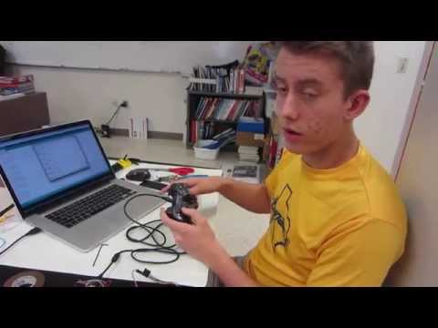
The second milestone for the balancing-robot project was controlling the motors with commands input with a PS3 Dualshock controller. The PS3 controller is connected via a USB cable through the Sparkfun USB Host Shield. I re-wrote a library from Github that was focused on receiving commands from the PS3 controller. My next step is to construct the frame for the robot.
1st Milestone:
The first milestone for this project was to be able to control the two 12 volt DC motors with code on the Arduino. I wrote simple Arduino sketch that used conditional statements and input from the Serial Monitor to control motor direction and speed. I’m really excited about this piece of the project, because it won’t be too difficult to translate the functionality of this code to allow me to control the motors with a PS3 Dualshock Controller via Bluetooth.
Starter Project: MintyBoost
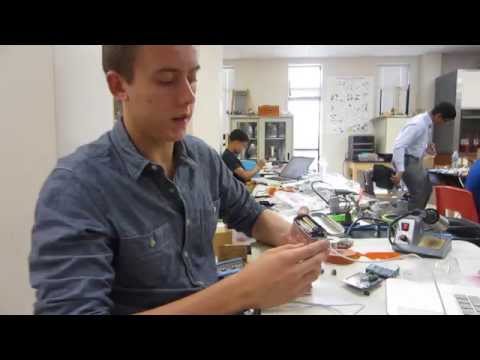
Upon arriving at BlueStamp, I completed the MintyBoost starter project to get acclimated to the engineering tools and ideas required in this program. I used capacitors, resistors, and integrated circuits to boost a 3 volt charge so that it could be used to power an iPhone/Android device via a USB cable. All of this was done on a compact board and was small enough to fit inside a box of mints. Overall, I built a portable USB charging device and familiarized myself with the components of a typical circuit.