Hi, my name is Tomás, and I am a rising senior at The Academy of Charter Schools. My starter project was the electronic die, which I chose because I enjoy playing and designing board games, most of which use the standard 6-sided die. My intensive project was a PS2-controlled omnidirectional robot, which is a robot capable of moving in any direction on a 2-dimensional plane by means of three special wheels. A later addition to the robot was a pre-designed robot arm, which was hacked to also be controlled by the PS2 controller.
Final Project: PS2-Controlled Omnidirectional Robot with Robot Arm
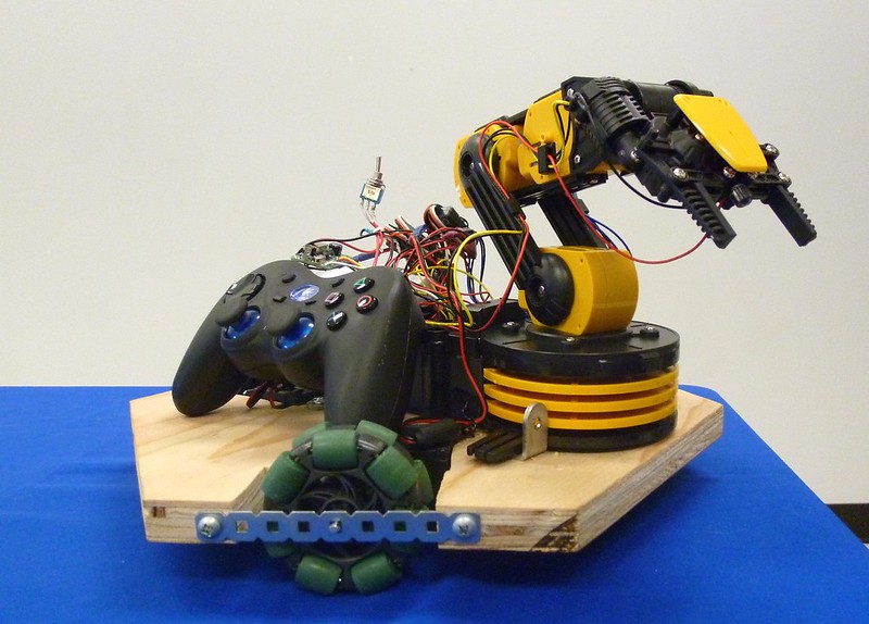
Milestone 5: The Final Robot
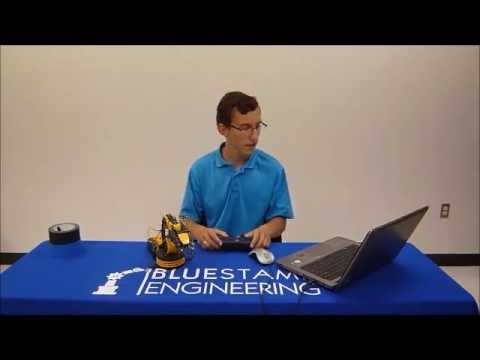
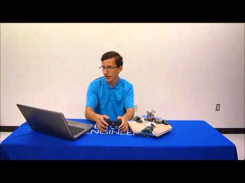
Finally, after 6 weeks of fiddling with electronic components and coding, I have a fully functional omnidirectional robot with an arm with 5 degrees of freedom (5+ if you count the LED…). In addition to moving in every direction, the base can rotate and move at variable speed based on the degree of inclination of the thumbpad. The arm assembly can rotate, pivot on three joints on the arm, open and close a claw, and activate an LED in the claw.
There were two main tasks to finalize the robot: to combine the hardware and to integrate the software. The hardware portion was more time consuming, mostly because I had to keep removing and remounting several pieces to access other hardware (after several repetitions, I left the entire thing unassembled until completion). I created a soldered version of the DIY motor controller from my fourth milestone, at the same time downsizing the circuit due to the lack of resistors. The internal battery wiring for the arm was removed and the battery housing was stripped of all battery mounts. The Arduino and DIY motor controller were just small enough to fit inside the battery housing, but some wires had to be redone so they could reach outside the casing. An eighth of a breadboard was used for the base motor wiring and battery hookup, and the adhesive on the bottom was used to mount it to the arm. A leftover piece of the steel braces used for the wheels was bent into a clamp to mount the battery on the robot. 1” 90-degree angle brackets were screwed into the wood base to secure the arm, with enough wiggle room for the arm to be removed if necessary. Also, a notch had to be cut into the plastic piece blocking the Arduino reset button because the Arduino has to be reset after being powered on in order for the PS2 receiver to turn on (this is due to an unknown bug in the PS2 library).
Writing the final software was the easier of the two tasks, mostly because the code for the two separate parts already existed. All it took was selectively cutting and pasting different sections from one code into the other, the entire process taking less than 5 minutes. However, when I went to upload the code to the Arduino, I realized that I had screwed the base in again… with the Arduino in the battery case. After unscrewing the battery housing and uploading the code, it was found that it worked as intended, but the “front” of the robot was one of the wheels, which made it a little difficult to control. The code was re-worked so the front of the robot was the side with the arm, making an easy reference point for any operator. A few more changes were made to the code to make arm control more detailed. While the directional pad on the PS2 controller lacked fine pressure sensing, it was enough to enable each of the arm motors (except the claw) to move at either a slow speed for precise positioning or a fast speed for quick transportation of the payload. When controlling the arm with the intended controller, it was found that by triggering the base and “elbow” motor simultaneously, one could make the arm move forward without changing the orientation of the claw. With the current PS2 setup, this was impossible due to the fact that only one of the three arm joint motors could be running at a time. The R2 and L2 buttons were then programmed to trigger this motor synchronization, while the directional pad retained control of specific arm joint motors.
Controls:
Left Thumbpad: Moves base in direction and speed indicated by thumbpad
Right Thumbpad Up/Down: Rotates base right/left in speed indicated by thumbpad
Left/Right Directional Pad: Rotates arm left/right; can be either fast or slow based on pressure applied
Up/Down Directional Pad: moves one arm joint forward/backward; can be either fast or slow based on pressure applied
R1/L1: Transfers Up/Down directional pad control to the next motor up/down the arm; when the end motor is reached, loops to other end
R2/L2: Moves the arm forward/backward without changing the orientation of the arm
Triangle/“X”: Closes/opens the claw
Square: Turns LED on/off

(click picture for a larger image)
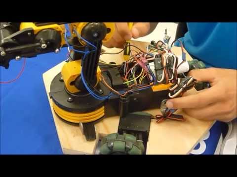
Milestone 4: The Fifth Motor
My fourth milestone consisted of gaining control over the fifth motor of the arm (the claw). The simplest way to achieve this would be to use two digital pins from the Arduino. By alternatively turning one on and the other off, they would either act as power or ground and cause current to flow in one direction or the other so the claw could open or close. However, the motor lead and the digital pin could not be wired directly together, because the motor pulled too many amps and would fry the pins. Similarly, the pins only supply 40 milliamps, whereas the motor needs 2-3 amps to run (1 amp = 1000 milliamps).
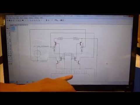
The first circuit tried was a simple H-bridge with transistors added to amplify the signal from the pins. This didn’t work because NPN transistors were used, and although they amplified the signal, they also acted as switches and blocked the current. PNP transistors (which turn ‘on’ when they receive a current of 0, versus NPN which turn on when a certain current is reached) were added to the circuit, replacing some of the NPN, but this setup, on top of not functioning, added two more digital pins from the Arduino.
At this point I started looking online for scratch-built motor shields. I found many different options, but most of them required hardware that was inaccessible due to the proximity of the end of the program. I eventually found a circuit that only used transistors, resistors, and diodes, but the author only supplied pictures of the physical circuit. I made a schematic on Eagle based on these pictures and built the circuit, but it only supplied 0.4V to the motor. Because of suspicion about the uncommonly high values of the resistors, I replaced the resistors with wires and turned it on again. This time, the motor received about 3.6V and moved! With control over the fifth motor, the final step is to mount the arm on the robot and solder the wires into permanent connections.

(click picture for a larger image)
Milestone 3: PS2-Controlled Robot Arm
This milestone consisted of getting a pre-designed robot arm to be controlled by a PS2 controller. A motor shield had to be added to the assembly to control the DC motors in the arm. After looking at the example code supplied with the motor shield library, it was fairly simple to combine that and the PS2 code from before to get the arm to move.
The only slight problem I had were figuring out that the VIN jumper had to be used and deciding on a controller configuration, because the PS2 controller only has so many buttons. The VIN jumper was a small piece of plastic that came with the motor shield that I originally disregarded as packaging or something similar. After the motor shield terminals didn’t work, and after a little bit of internet research, I found out that the piece had to be connected to two pins on the shield to make it work. After a few moments of panicked searching, I was able to find the piece and the shield terminals started working.
The main problem encountered was that the motor shield only supported 4 motors, while the arm has 5. After looking on the internet for solutions, I found a way to control a DC motor using two pins by turning one on and the other off (making it a ground). However, this did not supply enough voltage to power the motor. The next step is connect the fifth motor with the Arduino and attach the arm to the base.
Milestone 2: Using Thumbpad Input to Control Robot
After getting the robot to move and getting the PS2 controller to connect to the Arduino, it was simply a matter of coding to get the robot to move based on controller input. Because the PS2 library already received thumbpad input as x- and y-values, it would take only a small amount of trigonometry to convert these values into input values for each of the 3 motors. The problem was that the Arduino received the x- and y-values from a range of 0 to 255. While a fairly standard range, the nonzero center would make it difficult to input the values into trigonometric functions.
The Arduino “map” function was exceedingly important in this step, for it took values from a certain range and mapped them into another specified range. This allowed for the x- and y-values to be mapped onto a range with zero as its center, which then made them significantly easier to input into trigonometric functions. Even with correct motor input values, the robot still failed to move in a straight line. There were two main changes that eventually fixed this problem. The first was the realization that one of the wheels was not mounted on the center of the base’s side – it was half an inch off. This had the effect of causing that wheel to have a greater inefficiency than the other two, thus causing rotation during linear motion. By setting the other two motors’ power baseline lower than the incorrectly mounted motor’s, it evened out the irregularity and smoothed the robot’s motion.
The second modification that allowed the robot to move in a straight line was changing the function “[servo name].write(value)” to “[servo name].writeMicroseconds(value).” While the .write function has an input range of 0 to 180, the .writeMicroseconds function has an input range of 1000 to 2000. Even though they both have the same motor speed range (because the motor used is constant), the .writeMicroseconds function allows for much more precise control because of there being 1001 possible input values, versus the 181 possible for .write. It is analogous to the comparison of a bus to a car; a bus can only get you to the closest stop to your destination, while a car can take you directly to your destination. Having achieved omnidirectional motion based on thumbpad input, the next step is to add a robot arm to the system.

(click picture for a larger image)
Milestone 1: Autonomous Motion and PS2 Controller Link
It took several weeks and a few edits to the Build Plan to reach the first milestone. After getting the Arduino software to work on my computer, I hit a wall when I tried to work with the PlayStation controller. After a week of troubleshooting it was found that the controller I was using was in fact a PS3 controller, versus the PS2 controller required for the library I was using. While PS3 controller libraries existed, they could not be used without additional hardware. PS2 controllers were therefore ordered for me and the other 2 students who had the same problem.
Even after that the problems continued, but eventually another student and I were able to get the controller linked to the Arduino successfully. The problem was, my link stopped working after a few minutes while the other student’s remained functional. After spending another week troubleshooting, wires were finally soldered directly to the receiver, and this has seemed to fix the problem.
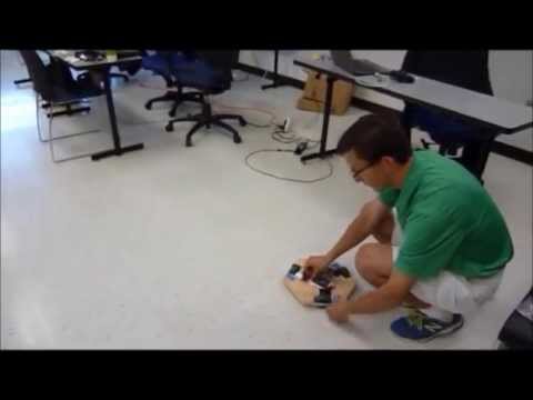
The second main obstacle encountered during the first milestone was getting the 3 wheels to work in synchronization. 2-wheel motion was achieved easily enough, as demonstrated in the video below, but when a third wheel was added, the robot did not move as intended. I recalculated the motor powers using around 10 different methods and got the same numbers every time. However, when these numbers were used, the robot moved in an arc. The next step in my project is to fix this problem and use the solution to link the PS2 controller to the robot.
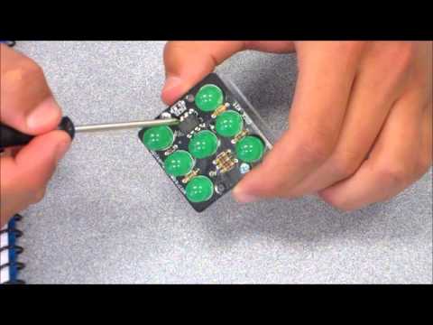
Starter Project: Electronic Die
The electronic die uses light emitting diodes (LEDs) to display a random number 1-6 in response to a moderate tap. The piezo glued to the base of the device produces a specific voltage when it experiences a large enough acceleration. The magnitude of the voltage varies depending on the direction and magnitude of the acceleration. It is this variance that allows for close-to-random results.
A resistor and a zener diode protect the microchip from being damaged by large amounts of voltage. The microchip receives this voltage and assigns a decimal value to it, which is recorded in 10 bits. It then takes the last 3 bits and reads them as a binary number 1-7. This number is then treated as one less, to allow for the appropriate results for a 6-sided die.
If the result is a 0, it is rejected and the voltage is reread. When a nonzero number is produced, the microchip lights up three of the four steps below to display the appropriate result. The three steps alternate so they appear as one cohesive display. If a result requires less than 3 steps, the “empty” steps are replaced with a pause – this ensures a constant LED brightness for all results.