Reflection
At Bluestamp, I like everything here- the classmates, the instructors, the projects, and a lot more. I was new to the area of engineering. During the time I am at Bluestamp, I learned how to use different tools, how to code, what different components’ functions are, and even how to do a better job on public speaking. When I was at Bluestamp for the first day, the only thing I knew was how to use the soldering iron. When I started to improve the function of NFC Computer Unlocker, I was thinking “how could I do that?” And now when I recall that period of time, I am proud of myself. Thank you, Bluestamp.
Third Milestone
Fingerprint sensor
↑↑↑↑↑↑↑↑↑↑↑↑↑↑↑↑↑↑↑↑↑↑↑↑↑↑↑
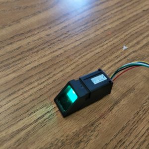
I did some modifications during the time. Except for the Arduino Leonardo and the RFID/NFC Shield, there are also two LEDs, two resistors, a proto-board, and a fingerprint sensor. The proto-board is to help connect the Arduino and the Shield to the LED and the fingerprint sensor. The purpose of using the fingerprint sensor is to make sure I am using the computer
The purpose of using the fingerprint sensor is to make sure I am using the computer unlocker, not anyone else. Now I cannot just directly make the unlocker type out the password when I put an NFC Tag beside the shield- I have to use the fingerprint sensor first. Usually, the red led is on. It means that the fingerprint sensor is on. When I put my finger on the fingerprint sensor, if the yellow LED is on for one second and the red LED is off, it means my fingerprint is detected. After that, if I put an NFC Tag beside the Shield, the unlocker will type out the password.
The greatest challenge during the time was combining the code for Shield and the code for the fingerprint sensor. I spent three days working on that. Also, I took a lot of time to program the Arduino.
Second Milestone
Software
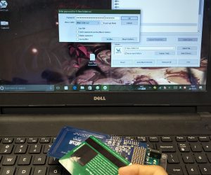
This is the second milestone of the project. I did some modifications on it. First, the NFC Tag is no longer attached to the RFID/NFC Shield but to another card which was in my wallet. Because without this modification, everyone could directly unlock my laptop using the NFC Shield only. Remember, the Shield would not work if the NFC Tag was not beside the Shield.
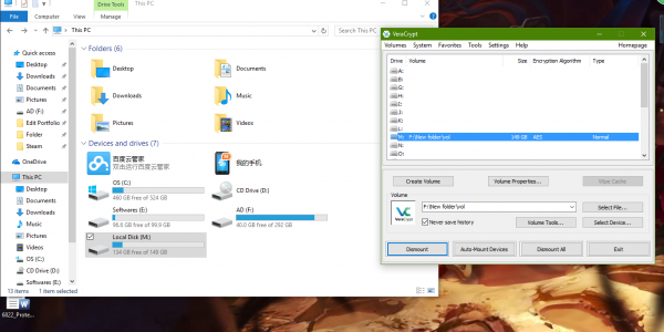
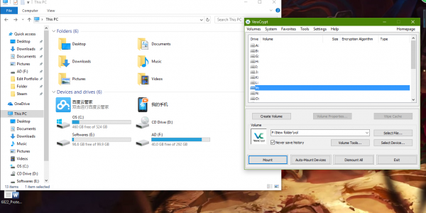
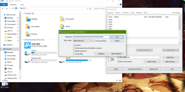
Let’s imagine if someone steals that card, they can still unlock my laptop. Therefore, I used an app called Veracrypt. It can create an encrypted virtual hard drive, and I can put all the important stuff in there. When I dismount the volume of the virtual hard drive, it disappears, and the apps in the disk can neither be found nor be used; when I mount the volume of the drive, Veracrypt will ask me to type out the password I set. For this password, I used another NFC Tag attached to another card and edited the code so that this NFC Tag can type out the password, like the other NFC Tag.
The challenge I faced was the process of creating the encrypted virtual hard drive. During the time Veracrypt was creating the encrypted virtual hard drive, the laptop turned extremely laggy and the process would last for 90 minutes. I couldn’t just sit there and did nothing, so I started doing my documentation. One hour later, however, my laptop crashed, and the process couldn’t be saved. Thus I had to start the process all over again, and I did it at home.
First Milestone
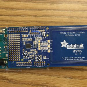
This is the first milestone of my computer unlocker. The computer unlocker consists of an Arduino Leonardo, a RFID/NFC Shield, and an NFC tag. An Arduino is the brain of a project. It can read the inputs and change the inputs into the outputs. RFID stands for Radio-Frequency Identification. It can read the stored information on a tag attached to an object. NFC stands for Near Field Communication. It enables two electronic devices to communicate with each other.
Connecting the computer unlocker with a USB cable, when I plug the other side of the USB cable into my laptop, the computer unlocker will automatically type my password out and unlocks my laptop. There is a wire connecting the digital pin #6 and the
On the RFID/ NFC Shield, the IRQ pin is tied to the digital pin #2 by default. However, the digital pin #2 is used for I²C on the Arduino Leonardo. I²C, or Inter-Integrated Circuit, is a protocol which enables “servant” chips to communicate with “master” chips. IRQ stands for Interrupt Request. It is a signal that temporarily stops a program and allows another program to run. I²C and IRQ are two different things, and this is why the Shield doesn’t communicate with the Arduino Leonardo on digital pin #2. Therefore, I cut the trace between digital pin #2 and the IRQ pin on the shield and reconnect the IRQ pin to the digital pin #6 by using a hookup wire.
Starter Project
Output
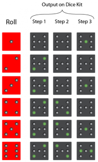
My starter project is to make an electronic dice. It consists of the base, the battery, the piezo, the diodes, the PIC chip, and several resistors.
The piezo is the main part of the dice. A piezo is a sensitive electronic component. When I hit the dice, the piezo vibrates, changes the kinetic energy into electronic energy, and then activates the dice. Every time I hit the dice, the voltage changes and the PIC chip gets the signals. The function of the PIC chip is to govern the operation of the computing system. This is why the numbers, or the signals, the dice shows is random. The picture left shows the outputs of the dice kit.
The LEDs and a small part between two LEDs are called the diodes. A diode is also an electronic component. Its two ends are called the anode and the cathode. The diode is directional. When the cathode is negatively charged, the current goes the right flow; when the cathode is in a positive charge, the current goes the wrong flow.
There are also some four-band resistors. The bands are colorful. Different colors represent different numbers. The first two bands represent digits, the third band represents multipliers, and the last band represents tolerance. For instance, a resistor colored brown-red-orange-gold would be 12kΩ with a tolerance of +/- 5%.
The biggest challenge during my project was desoldering a diode. A diode is directional, but I soldered the diode in the wrong direction, so I had to desolder it. This process spent me nearly two hours.


