
LED Necktie that Lights Up Based On the Volume of Your Voice


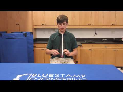
I’m Tim and I am going into 10th grade at Regis High School. For my starter project, I built the Electronic Dice Kit, which is a cube with LEDs that light up like the face of a die when tapped against the table. For my main project I built a LED necktie that lights up based on the volume of your voice. I chose this project because I wanted to build something fun and interesting that I could use in my everyday life.
Building this tie, I have learned about electrical components, circuits, and especially about coding Arduino, which I knew nothing of when I entered BlueStamp. BlueStamp has been an extremely valuable opportunity for me, as it showed me that engineering is something I may want to pursue in the future.
Final Video

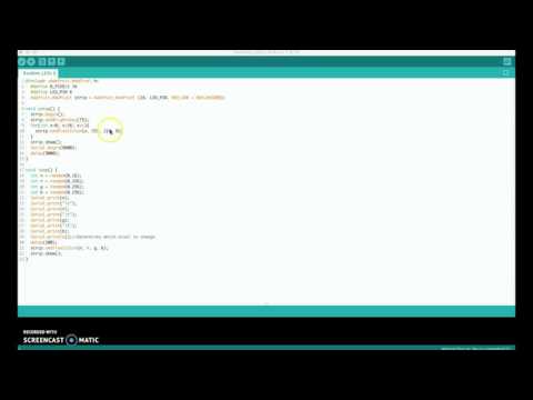
I coded my tie to display the volume of my voice as a fluctuating line of NeoPixels. The microphone detects noise around it and transmits the value to the Arduino, which determines whether or not I am talking using a threshold of 600. The Arduino then transmits that value to the NeoPixel chain, which displays the outcome. The final code and BOM are below.
Second Milestone
Since my first milestone, I fixed more NeoPixel wiring problems and coded the NeoPixels to light up in a random rainbow pattern. I found that the connections between pixels were not secure enough to transmit a signal because the thread kept lifting off of the conductive pads. I fixed this problem by soldering the threads down to the data, power, and ground pads on all 16 of the pixels. I then developed a code for the NeoPixels that created 4 random numbers: one specified which NeoPixel would change color, and the other three specified which RGB color that pixel would change to. The code is attached below.
Besides the NeoPixels, I changed my battery and sewed the microphone onto the tie. I swapped out my 3.7V battery pack for a 5V Anker PowerCore+ Mini because my Flora did not have enough power to supply to both the 16 NeoPixels and the microphone (now sewn with its breakout board to the knot of the tie).
First Milestone

For my first milestone, I have sewed all 16 of the NeoPixels and the Flora microcontroller onto the tie without shorting the circuit. This was a challenge because the conductive threads for the ground, power and data lines needed to be close together (within 1/4 of an inch of each other), but could not cross. At first I was unaware of this problem, so after I sewed on 8 of the pixels I separated the threads with electrical tape, but they were still touching. I then tried to use heat-shrink to contain the tail-ends left over at the knots on the ends of the threads, but the threads continued to cross. I found that I also sewed the pixels backwards, with the small arrows indicating data flow facing down, not up and had to remove the 8 pixels and start over. This time, however, I sealed the knots in the conductive thread with instant-dry nail polish and used regular thread to keep the rest of the conductive lines separate, and the circuit did not short. My original design was similar to the image below, with the exceptions that I used an Adafruit Flora (not a Lilypad) and that the wiring was slightly different (common ground line, common power line, separate data lines between pixels) because I used sewable pixels.

My original design was similar to the image above.
Starter Project

For my starter project, I chose the Electronic Dice kit, which lights up like the face of a die when it is tapped on a table. When it hits the table, a piezoelectric sensor on the bottom generates an electric signal that turns on the PIC microcontroller. The PIC generates a random 10 bit binary number, takes the last 3 bits, and converts them into a decimal number from 0 to 6 (zeros are re-rolled). The PIC coordinates the LEDs to light up in the proper pattern using power from the battery underneath. After 15 seconds, the PIC goes into sleep mode.