Tatiana P.
My name is Tatiana, and I am rising senior at The Chapin School. This summer my intensive project was a 3D printed gesture control hand and my starter project was the mini pov 4. Through these projects I challenged myself to learn and problem solve independently.
Engineer
Tatiana P.
Areas of Interest
Mechanical Engineering
Biomedical Engineering
Chemical Engineering
School
The Chapin School
Grade
Incoming Senior
Reflection
Through my experience at BlueStamp I have learned a lot about myself as an engineer. Coming into this program I was completely sure that I wanted to study biomedical engineering in college, but after working with mechanical and electrical engineering on my project, I have found that I do not want to go into college with such a narrow field of study. Now I am looking forward to being able to explore different types of engineering and not having to specify my studies right away. I have really enjoyed the BlueStamp environment where even if we all had different project the students were willing to help each other and where the instructors set you in the right direction but encouraged you to find out the answers for yourself. I was able to problem solve and think independently. I wanted to push myself to persevere through these challenges, so that when I was able to solve problems in my project I had a greater feeling of accomplishment. My greatest challenge I faced while at BlueStamp was my project not working the day of my presentation. One of the servos stopped working because I did not have a voltage regulator in my circuit, and it was overloaded. That day I had to figure out what a voltage regulator is and how to use it in a circuit. When I presented and my project finally worked I was so proud that I was able to overcome this challenge. Another challenge I faced was trying to implement NRFs in the circuit. I was able to complete the circuitry and code but unfortunately there was not enough time to debug it and figure out why the NRF attached to the glove was not transmitting. I hope to continue to work on the NRFs after BlueStamp is over. It is hard to believe that my time at BlueStamp is coming to an end, but now I am excited for all that I will be able accomplish with engineering in the future.
Final Project
Documentation
- Bill of Materials (BOM)
- Code
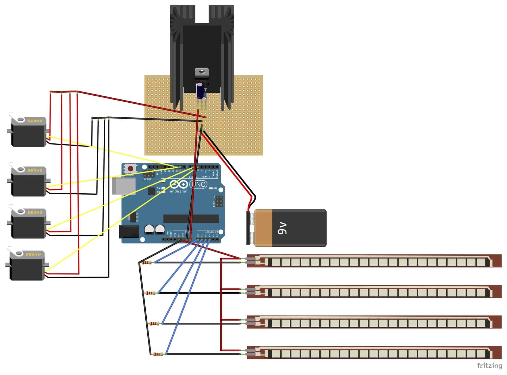
Schematics