


Introduction
My name is Tanvi. I go to Scarsdale High School and I’m in the class of 2017. For my starter project I made a TV B Gone, which is a device that allows you to turn on or off almost any TV. For my main project I made the gesture controller RC car with a robot arm.
Reflection
I was ultimately very happy with my experience here, at BlueStamp Engineering. The learning environment was unlike any other I have experienced before. I was forced to really think for myself and answer my own questions using resources like the internet, rather than depending on someone else to supply me with answers. I am extremely grateful for this lesson as I know it will be useful in the future when I start working on projects independently. The experience of building my own project using coding, electrical engineering, and mechanical engineering has given me the confidence and faith in my skills to start thinking about project ideas I would like to build independently.
Final Milestone
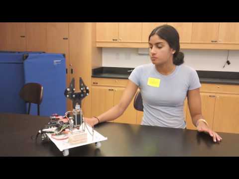
Since my last milestone, I have added an ultrasonic rangefinder to my gesture controlled RC car with a robotic arm. Now, the cart will stop whenever the front comes within 10 centimeters of any object. To add this feature, I simply mounted the ultrasonic range finder and modified the coordinator code to read the distance detected by the rangefinder and stop the motors if that distance is less than or equal to ten centimeters. Here is the modified coordinator code:
I also replaced the 2 inch diameter wheels that were originally attached to the DC motors with wheels of diameter 4 inches. I did this to increase the speed of the cart (greater diameter allows the wheels to cover more ground while RPM is constant). I created a CAD sketch of these new wheels using OnShape. Here is the CAD file:

These wheels were laser cut out of plywood. I then had to coat the wheels in rubber sealant to give them traction against the ground.
Finally, I added a 5V battery to my cart that only supplies power to the servos on the robotic arm. I did this because the robotic arm was not working properly when it was sharing a power source (12V battery) with the DC motors.
Schematics
Here are the schematics for my glove and cart:


Second Milestone and Third Milestone
For my second milestone I was able to control the DC motors using the flex sensor wirelessly. First, I attached my DC motors to an H bridge because, not only did that allow the DC motors to rotate forwards and backwards, but I needed to supply the DC motors with 12 volts. After I did that, I wrote a code that tested out the motion of the DC motors when a certain flex sensor was bent. This was similar to my first milestone in which I controlled the motion of the robotic arm using the flex sensors. Here is the Arduino code:
After I tested the motion of the DC motors, I had to split this code up into two parts- one part that would take the reading of the flex sensor (router) and one that would read these readings and the instruct the DC motors to rotate a certain way (coordinator). Once I did this, I had to instruct the XBee on the router to print a certain character when a certain flex sensor was bent. I also mapped the values of the flex sensors down to a smaller range so that it would be easier to classify when a flex sensor was bent or straight. Here is the router code:
For the coordinator code, I used something called a Switch Case, which allowed the Arduino to instruct the DC motors to rotate either forwards, backwards, left, or right depending on what character was sent by the router and read by the coordinator. Here is the coordinator code:
After I completed the code, it took some troubleshooting and slight modifications of my code to make the motors respond accurately when I bent certain flex sensors.
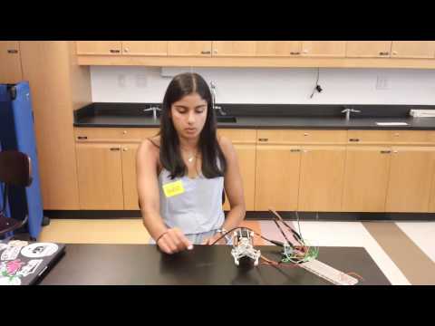
For my third milestone I was able to control both the robotic arm and the DC motors, wirelessly, using the flex sensors. To do this, I had to modify my code from my first milestone, which allowed me to control the robotic arm using the flex sensors from the same Arduino, by splitting the code in the same way I created the code from my second milestone. I created a router code, which read the values of the flex sensors and sent a certain character when a certain flex sensor was bent, and a coordinator code, which read these characters and instructed the robotic arm to move accordingly. Here is the router code:
Here is the coordinator code:
Once I was able to control the robotic arm wirelessly and the DC motors wirelessly, I then had to combine the router codes and the coordinator codes so that I could control them both from the same code. To do this, I copied and pasted the router codes into one code. All I changed was four of the characters that were sent when a certain gesture was performed, so that I had eight separate characters for eight separate gestures. I also had to make my gestures more specific so that the XBee sent the correct character for the correct gesture. Here is my final router code:
After that, I combined the coordinator codes. I changed the characters in the switch code accordingly. Here is my final coordinator code:
Once I had these codes, I did some more troubleshooting and changed parts of the code to make the motors and claw work more efficiently. I had to replace my original claw because the servo stopped responding, but the new one works well. I am still having trouble telling the robotic arm to bend all the way forwards, but I intend to fix this for my final product. I also plan to add an Ultra-sonic range finder to my cart so that it can detect how far it is from an object.
First Milestone
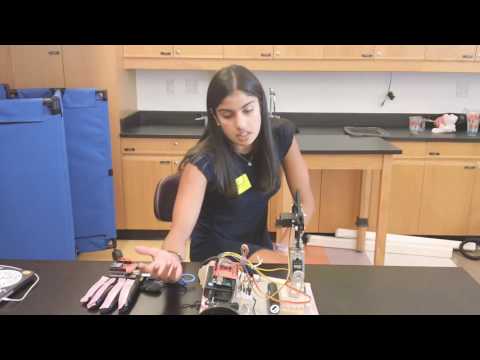
For my first milestone I was able to control the servos on the robotic arm using the flex sensors, which allowed me to open and close the claw as well as move the robotic arm along the horizontal axis. There were many small steps that I had to complete in order to complete this milestone. First, I had to familiarize myself with the way flex sensors work as well as make sure my flex sensors were working properly. To do this, I wrote a code on Arduino that allowed me to see the resistance readings of each individual flex sensor when they were bent and unbent. Seeing a change in the resistance values when the flex sensors, when they were bent versus straight, allowed me to conclude that my flex sensors were working. This is the code I used to record the reading of the flex sensors:
After I tested the flex sensors, I became more familiar with how servos work. After learning about the function of servos, I tested the servos that were attached to the robotic arm using the sweep function on Arduino. By doing this, I was able to make the robotic claw open and close and rotate the base of the arm using Arduino commands. This is the code I used to test the servos:
After I was sure that both the flex sensors and servos were functioning correctly, I started working on the code that would allow me to control the motion of the robotic arm using explicitly the flex sensors. Writing code that worked took some trial and error, but eventually I was able to come up with this code:
Flex_Sensor_and_Robot_Arm_2.ino
Starter Project
For my starter project I made the TV B Gone. The TV B Gone is a device that allows you to turn off almost any TV using infrared rays. I was able to learn a lot about the function of transistors, oscillators, and microcontrollers, not only in general but, with respect to the TV B Gone. I also became more aware of the importance of the placement and orientation of certain parts. For example, parts such as LEDs are polarized, and placing them on the board incorrectly could damage them.