Madbot
The Madbot is a multi-functional robot with seven modes. The parts for building this project can be found on Madlab. With the keyboard attached the Madbot can be completely controlled, or switched to a different mode. By using the arrow keys on the keyboard the Madbot can be moved around and speed can be increased using shift. The different modes can be activated by pressing the function keys F1-F7.
F1 is “roam mode” where the Madbot moves forward until it comes across obstacles and avoids them. F2 is “maze mode” where the Madbot moves forward until it hits a wall and then moves along that wall. F3 is “push mode” where Madbot searches for objects and then pushes them. F4 is “avoid mode” where the Madbot waits until it is approached and then takes avoiding action. F5 is “light mode” and in it Madbot searches for areas of light. F6 is “dark mode” where Madbot searches at random until it finds an area of dark. F7 is “dance mode” where Madbot will play back a sequence of moves that has been integrated by the user. The sequence of moves can be integrated by pressing shift F7 and recording a sequence of moves for Madbot to follow.
In normal functioning this robot contains resistors which dissipate energy. In addition to this there are capacitors which store energy. The infrared transmitters and infrared receiver are crucial especially for the first four modes. Infrared is emitted and reflected back into the receiver. Once this happens the infrared receiver sends a signal to the microchip which then sends a different signal to the motors depending on the mode.
Another important component is the LDR (light dependent resistor) which gives Madbot the ability to react when there is excess light or no light. This is because in a light dependent resistor, the intensity of light and resistance of this resistor are inversely proportional so as the intensity of light goes up, the resistance goes down. In light mode, when Madbot comes into an area of light the LDR allows current to get to the microchip but the microchip stops any more current from getting to the engines. In dark mode when madbot is in an area of dark the resistance for the LDR is at its max and allows not enough current to power the engines. There is also a voltage regulator and its job is to convert the 9 V power source to be used by the circuit components such as the LEDs which require 2 V-3 V and the motor which requires 9 V-12 V. There is also an outlet for connection to a keyboard.
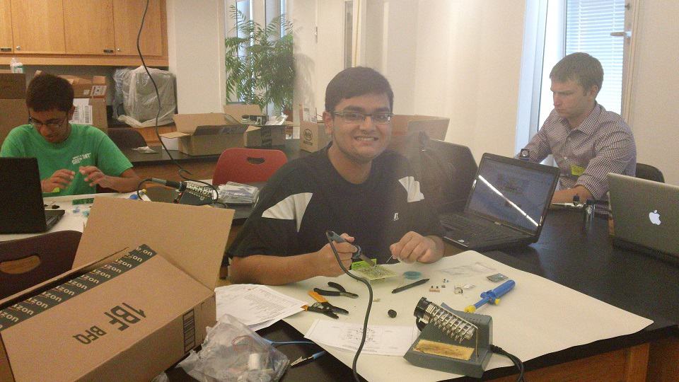
Some improvements I would make is to read through the construction rather than just reading the symbols on the circuit board and soldering them. This is because the construction provided gives helpful tips such as to not attach the engines to the gearbox first but to the capacitors in the circuit. This would have made completing construction much easier.
IR Vision Rover Robot
The infrared vision rover robot kit is a rover with the ability to move in linear motion and change its direction when a macroscopic object is placed in its way. I received the parts for it from apogee kits. When functioning normally, the resistors which dissipate energy and allow the circuit to be completed, transistors which change electrical signals and capacitors which store electrical energy and also contribute to completing the circuit allow for electrical flow to get to the engines, the speaker which makes a clicking sound, and all LEDs (light emitting diodes) located in the center of the circuit board.
Normal functioning changes however when a macroscopic object is coincident upon the rover’s path because the right engine (relative to the forward movement of the rover) starts to go in the reverse direction and the left engine (relative to the forward movement of the rover) stops. This happens because first the infrared light (which is the light that humans generally can’t see but is a wave that can reflect off any object on earth) emitted has been reflected back to the infrared receiver. Then the infrared receiver’s resistance decreases allowing current, which is the flow of electricity, to get to the microchip and red LED. When this happens the microchip signals the relay which is a circuit component that is activated by a signal to open or close another circuit component and in this case the relay opens the signal to one transistor. Before this process began, the electrical signal was being sent to both engines but the object being placed in the way of the rover causes the left engine to be completely cut off from the electrical signal and the right engine to reverse its direction of spin. The rover would turn left and when there is no object in the way of the rover, the rover would continue in linear motion.
When construction was complete there were some issues because the rover was not functioning the way I wanted it to. When I turned it on, the LEDs were not lighting up and engines were not changing direction when a massive object was placed in front of the rover. I noticed one mistake immediately which was that the microchip was oriented the wrong way. This caused signal to the relay to not be sent. Even after I noticed this mistake, the problems were only partially fixed because the engine was still not reversing its direction. After meticulously analyzing the circuit I noticed that some terminals of the transistor and infrared receiver were not properly soldered but still touching the conductor. The solder is important because it allows a securely fitted pathway for electrons to flow.


