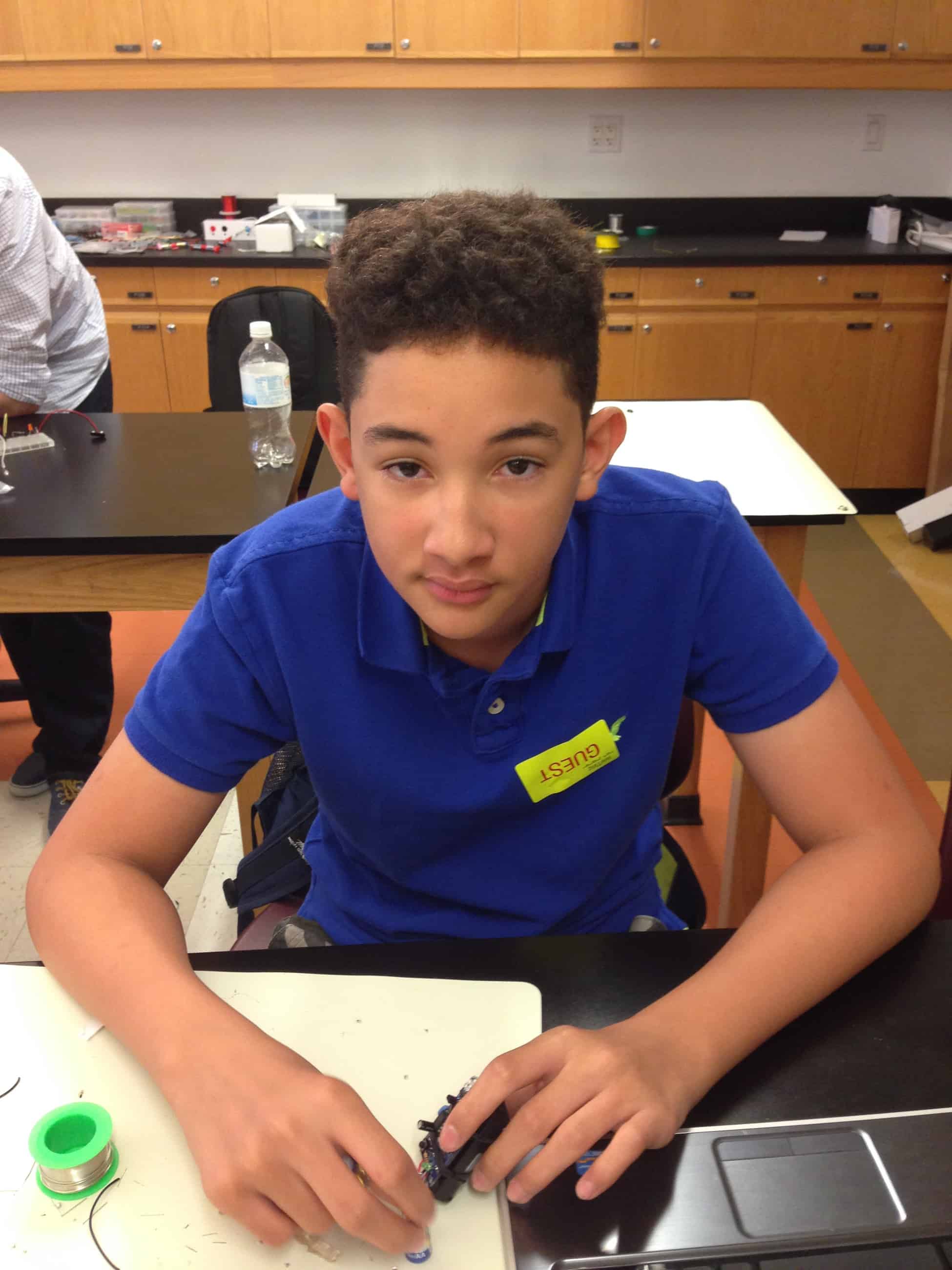
Hey! My name is Steven and I am a raising sophomore at KIPP NYC College Prep High School. My days at Bluestamp Engineering were amazing. I had lots of fun while learning at the same time. For my starter project I chose the TV-Be-Gone kit. For my main project I chose the Raspberry Pi touchscreen camera touchscreen.
____________________________________________________________________________________________________________
For my main Project I chose the raspberry pi touchscreen camera. I used the Raspberry Pi model B+. The Raspberry Pi is like a mini computer with a 700MHz Broadcom BCM2835 Processor and 512MB of RAM. I am using the Raspberry Pi to house the software of the Camera and pictures. I downloaded the OS Raspbian Wheezy with the PiTFT touchscreen calibration already installed. The touchscreen i used was the 320x240 2.8″ TFT+Touchscreen for Raspberry Pi.
Because I used the Raspberry Pi model B+ for my camera, the PCB hangs over the USB ports by 5 millimeters, so I couldn’t use the 3D printed case made by Adafruit. Instead of staying without a case, I designed the case using Sketchup. I printed the case I made in glow in the dark plastic. A complication I had was that the holes I made for the ports were shifted by 7 millimeters to left of where they were supposed to be.
Documentation:
Tutorial: http://bit.ly/1HSvpx4
BOM: http://bit.ly/1JUDFx0
3D Case:
My name is Steven and I chose the TV-B-Gone starter Kit. I was able to turn off the TV in the lobby of the school. When the security guard was not looking, I pressed the button and it took about 30 seconds for the TV to turn off.
The TV-B-Gone is supposed to turn off most TVs. I started by looking at the documentation online and then I studied the PCB board. After that I put in the resistors, capacitors, oscillator, IC chip, LEDs, and the transistors. I used 5 transistors, 2 resistors, 2 capacitors, 1 oscillator, 5 LEDs, 1 8-pin IC chip, and a battery holder that holds 2 AA batteries. This took me about 20 minutes to solder everything in place carefully. The 4 biggest LEDs( Light Emitting Diode) are IR blasters that signal the TV to turn on and off. The IC chip is like the brain of the TV-B-Gone, it stores 115 different codes to turn off different brand TVs. The button closes the circuit so that the chip can send the codes to the transistors. The transistors then boost the current to the LEDs so that the LEDs light up in the same sequence of the code that was sent by the 8-pin chip. The oscillator is the blue little ceramic circle next to the IC chip that oscillates the current when the button is pressed. Its like a time keeper for the current in the gadget. The oscillator acts like a timer for the functions of the gadget. Also, the resistors and capacitor play and important role in the kit. The resistor resists the amount of current flow to the LEDs so they don’t overheat and burn out. The electrolytic capacitor is used as timing elements in conjunction with a resistor network. All these steps happen in a matter of 52 seconds (if the TV-Be-Gone goes through all the codes).
A complication I had was keeping the solder iron tinned and carefully placing the solder in the board so that it wouldn’t go into other tracks in the circuit board.


