INTRO
Hello, my name is Stephan and I am a rising junior at The Urban School of San Francisco. My starter project was a student-defined project where I decided to build an automatic tea steeper. This tea steeper lowers and raises a tea bag into a mug by using a servo controlled by an Arduino running on a timer code. For my main project, I am building a camera stabilization gimbal which will be used to stabilize a camera while the user is holding the gimbal. The reason why I chose this project was because I wanted to experiment with hardware and software and learn to test code while also getting to design and work with hands-on electronics.
MAIN PROJECT
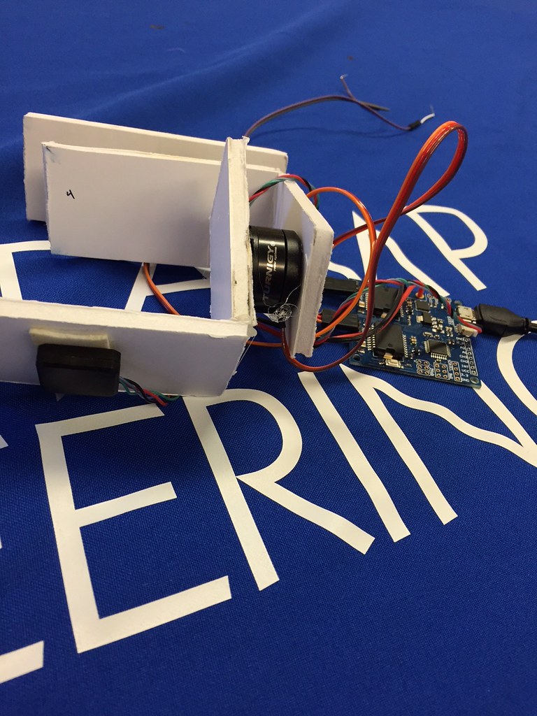
My main project, the automatic stabilization gimbal, uses two brushless motors to maintain a consistent position for a camera. Both of these motors are mounted onto a chassis fit for the motors, battery, controller, and the IMU (Inertial Measurement Unit). The controller relays specific pulses of electricity to the motors to compensate for the smallest movements. The code is uploaded to the controller which acts as the brain for the gimbal. The IMU contains an accelerometer and a gyroscope which measures the pitch and roll of the gimbal as a whole. These values that the IMU captures along the X, Y, and Z axis are sent to the controller. The controller processes these changes and sends live values to the motors in order to control and maintain the gimbal automatically. The pitch and the roll information from the IMU is sent to the two brushless motors. This allows the camera on the gimbal to be completely stable and maintain its position even when the camera is being moved or tilted.
This is my final video for my BlueStamp student-defined project this year. Throughout this process, many of the steps were definitely challenging but I am very proud of the final project. There are a few parts of the project I would like to manipulate and add to in the future. When starting the project, it was very difficult to get my foot in the door as I did not fully know what I was doing in terms of the software and the code. Because of minimal documentation for previous like projects, I had no guide to go back and help me. I faced many challenges throughout the development of this project, whether it was faulty parts or not having the correct computer to run the software. The most difficult challenge that I faced was not getting the IMU and controller to be recognized by the GUI (Graphical User Interface) software. The GUI allows me to change the PID values and manage the signals which are sent to the two motors. PID stands for proportional–integral–derivative and the tuning of these values allows for the user to create more stable electronic pulses coming from the controller. Although I did not write the complete set of code, I needed to manipulate many of the lines and components so that my project would work with my dimensions and with my specific components. Having not taken calculus, the tuning of the PID values were very difficult to manipulate. Finding each value for PID was necessary to create a uniform pulse going to the motors.
BILL OF MATERIALS
GIMBAL CHASSIS PROTOTYPE

This is the prototype for my final chassis. I made the first prototype out of cardboard so I could easily move the motors and recut the dimensions to make it most efficient.
INSPIRATION / INSTRUCTABLES PAGE
The person who created this Instructables page had very poor documentation so it was nearly impossible to follow along with his process. Although I used a lot of the same components that he used, I needed to do all of the eperaminting through trial and error with the software and code.
PARENTS NIGHT PRESENTATION
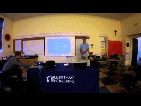
As a second year BlueStamp student, I took the opportunity to expand to a business focused presentation. After making my camera stabilization gimbal, I prepared my final presentation to focus more on the threshold between medicine and engineering. For example, an eating utensil for Parkinson’s patients and a stabilization gimbal use very similar fundamental technologies and function on a very similar scale. In my presentation, I pivoted my focus to the field of this eating utensil because there is great opportunity in this market. There is one company which has developed something very similar which was part of my inspiration. Liftware is a company which has created a utensil for Parkinson’s patients so their eating can be more convenient and ultimately solving their disability for one simple task. The technology that they use is very similar to my system and the program I used in my project.
Below is video of my presentation:
MILESTONE 2
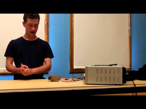
This is my second milestone. Since Milestone 1 I was able to create a cardboard gimbal chassis and continue to modify the PID values on the GUI software. Also, my new motor came in the mail so I was able to use it as the roll motor. In my second milestone both of my motors have the capability to move very smoothly. I still need to work out some sensitivity problems with the IMU because right when I tilt the IMU 90 degrees, the motors will continuously move. There are still some errors which I will need to fix but I was able to chance a lot of the PID settings on the software since milestone 1. Also, I am going to test placing the IMU in different places around the gimbal. Right now I have the IMU on the table and I am manually controlling it. I think that if I was to tape it to the bottom of the pitch axis the response would be more accurate.
MILESTONE 2 VIDEO AND DEMO
MILESTONE 1
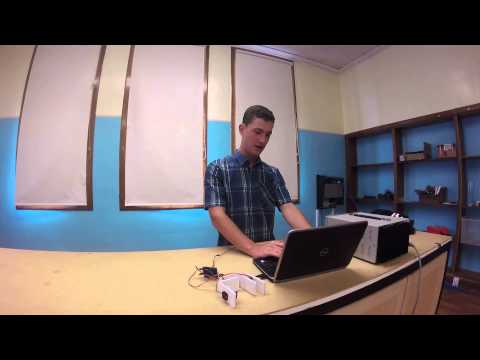
This is my first milestone of BlueStamp this year. For my first milestone, I was able to get the pitch and roll motors to change in response to the change in position of the IMU. Both the pitch and roll motors move differently depending on the change in axis values sensed by the IMU. I used the power source to increase the power going through the controller and to both of the motors. Originally I was just using the 5V from the USB port on the computer which was unable to control both of the motors. As I increased the voltage from the power source, the motors moved more vigorously and their movement was more pronounced. One of the motors that I used in my demo video did not work and I knew this because I tested it on both of the motor ports. But, I have a new motor in the mail which should solve this problem. My next milestone will be when I complete the draft of my camera chassis and when I get my new motor.
MILESTONE 1 VIDEO AND DEMO
STARTER PROJECT
My starter project is an automatic tea steeper. To do this I needed to write a code which would allow the push of a button or a flick of a switch to specifically control a servo. I needed the servo to move from 90 degrees to 0 degrees at the push of a button. Then it needs to wait for 3 minutes and then return to its starting place. Coming into this program I did not have a lot of experience with coding and programing so I used pre-existing codes and manipulated them so they would fit my project specifically. I ran into many problems with the button I was using because my pervious code raised and lowered the arm when the button was pressed so that even the smallest movement of the table would cause the arm to raise and lower uncontrollably. To fix this I needed to debounce the button to make sure that it would only activate the servo if it was pressed for a specific amount of time. After trouble shooting the code and creating the circuit, I have a working project which I am proud of.
STARTER PROJECT VIDEO AND DEMO
STARTER PROJECT SCHEMATIC AND CODE

