Magic Mirror
A magic mirror is a two-way mirror placed in front of a monitor which is powered by a Raspberry Pi. Light from the monitor shows through to the mirror, so the mirror appears to display whatever is on the monitor.
Engineer
Sophie H
Area of Interest
Art History
School
Lowell High School
Grade
Incoming Senior
Reflection
Final Milestone
Motion Sensing
Voice Controls
Motion sensors are often used to save electricity and to make your life more efficient, like lights that turn on when you walk by or paper towel dispensers that dispense towels or hand dryers that dry hands. I wanted to implement this technology into the magic mirror so that it will turn off when there isn’t anyone around and turn on again when there is.
Voice commands can make anything cooler. They can also turn a normal mirror into something like the magic mirror from Snow White.
Materials
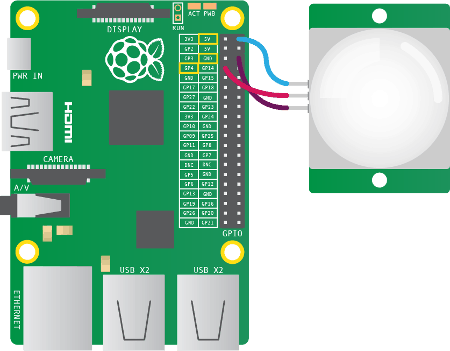
PIR Sensor
– ‘PIR’ stands for ‘passive infrared.’ Infrared light or infrared energy is emitted from warm bodies, like animals or humans.
– PIRs are made of a pyroelectric sensor. They’re great for detecting motion because they look out for changes in their environment in the form of heat. When there is a sudden temperature change, the PIR can infer that there is motion and sends signals through the pins.
– PIRs detect change using data from its two halves. The sensor is separated so that if one half detects more radiation, it knows something has changed and outputs a signal.
– The sensor is covered by a Fresnel lens. The Fresnel lens helps to focus incoming light, so the sensor can extend its range of detection.
Microphone
– A microphone is important for voice controls. It takes audio input so that the computer can process it and pass it through code and transform it into digital commands.
Speakers
– Speakers are handy for aural feedback for a smoother workflow. The voice control platform I chose was Amazon’s Alexa, which emits a tone whenever you invoke it and can also speak responses.
Setup
Wiring the PIR sensor to the Raspberry Pi pins seemed simple but was not easy. I wasn’t used to working with non-software stuff, so I depended a lot on Google.
How I Did It
Initially, I thought implementing a PIR sensor would be easy because there was already a MagicMirror module made specifically for this. So I downloaded the PIR module the way I had done with all the other ones: I git cloned it into the ‘modules’ folder and added its entry to the ‘config.js’ file.
Then I covered the PIR sensor with paper to see if the monitor would turn off. It didn’t work so I gave up. I wasn’t sure whether it was because of my wiring or my code or my PIR sensor.
I found another script for motion detection with the Raspberry Pi. I downloaded the ‘pir.py’ code from there and then edited the crontab, which will run the script on boot. I wrote the ‘monitor_on.sh’ and ‘monitor_off.sh’ bash files which ‘pir.py’ will execute depending on what it senses from the PIR sensor. These two scripts used the ‘tvservice’ command which controls the HDMI output to the monitor.
Finally, the display would turn off when there was no motion and turn on again when I waved my hand in front of it. But, there was still a problem. When monitor came back to life, the display size and resolution would look different. This was because tvservice powering off the monitor erases the framebuffer, or, data of what the screen should look like at the moment.
I tried using ‘fbset’ to reset the framebuffer, but I still could not get the monitor to look right. Looking for other solutions, I saw that many people recommended using the ‘vcgencmd’ command over ‘tvservice’ in order to avoid deleting information. After implementing this alternative, everything was perfect. The PIR was able to detect motion and send data through the GPIO pin to the ‘pir.py’ code which decides if it should turn the monitor on or off.
Future Modifications
My next step is making this magic mirror even more magical. I’d like to add gesture controls for hands-free operation as well as facial recognition for a customized experience. As far as physical features, it’d be really cool to add an LED light strip around the frame for a kind of halo effect and program it to change colors or respond to music beats. Also a power button.
Second Milestone
Disassembly
This was the scariest part of the whole project. My first step in making the physical frame was stripping the monitor of its bezel. To do this, you need some hard flat tools and finesse, like in the video to the right. When I tried to do this with my own monitor, I forgot to unscrew a screw and I applied a lot of pressure and when I powered on the monitor half of the screen was not working and one corner was like totally blown-out white.
A couple weeks later, I got a new monitor (thank u) and tried it again, and this time without breaking it.
Next I had to replace the cabinet mirror with the two-way mirror. To do this, I used a flat head screwdriver and tried to pry off the top piece of wood. I did a lot of damage to to surrounding region of the frame (check out the pics below), but wood glue is pretty neat.
Installation
Once I got the two-way mirror in the cabinet window, everything else went well. I centered the monitor horizontally to the mirror and secured it to the frame using duct tape. It seemed pretty safe.
Then I hooked up the monitor and the Raspberry Pi, plugging in their power supplies to the two-way power splitter, connecting them with the VGA cable and HDMI-VGA adapter.
First Milestone
My first milestone is running the web server on the Raspberry Pi. This is the entire software part of the project. The mirror interface that I used was MagicMirror. The things that I used for this milestone were:
- a Raspberry Pi,
- an LED monitor, and
- a wireless keyboard and mouse.
Research
Before BlueStamp began in the summer, I did lots of research on how to build a magic mirror, mostly to see if it was easy enough for me to do. On the internet, I saw lots of people’s builds and it was inspiring to see their dedication and creativity. I saw that it was a mostly software project, which made it less intimidating. In hindsight, I wish I had the opportunity to work more with hardware.
I adapted the parts list from Evan Cohen’s Smart Mirror documenation and planned on using Michael Teeuw’s MagicMirror platform. I compiled this information into a Bill of Materials and a Build Plan. Several weeks and one starter project later, I started building my very own magic mirror.
Setup
I started with connecting the Raspberry Pi and the monitor. The wireless keyboard and mouse can both be connected to the Raspberry Pi with USB receivers. The Pi came as part of a starter kit which also had an SD card, a charger, and an HDMI cable. I inserted the SD card into the Pi and then connected it to an outlet with the charging cable. After that, I connected the Pi and the monitor with the HDMI cable. Then I plugged in the monitor’s power cord to an outlet as well. Now all the parts are connected.
Installation
The next step was to set up the mirror interface on the Raspberry Pi. I followed this tutorial. This guide helps with installing the Magic Mirror platform made by Michael Teeuw. I chose to go in this direction because I wasn’t sure how to code the display from scratch and because Magic Mirror is well-documented and has a lot of implementable modules for lots of customization. Setting up the Raspberry Pi and the mirror interface meant learning how to navigate the Linux terminal and how to use various bash commands. After successfully installing everything, I could run Magic Mirror for the first time.
The Magic Mirror platform is based on Electron, which is a framework for web applications. Basically, it is a bundle of various software (languages, libraries, etc) that help create the skeleton/design of the application. Electron uses the standard web languages JavaScript, HTML, and CSS.
Configurations
The most time-consuming part was configurations and customizations. I changed the font by editing the .css file. Then I moved on to the modules. I found a lot of modules made by other mirror people here. Using them required two steps: downloading the code and adding it to the mirror. I used the ‘git clone’ command to clone the repository into my ‘modules’ folder. Each module has some documentation with what code to add to the ‘config.js’ file. So you gotta do that. The ‘config.js’ file contains an array of all the modules to show on the display page. I installed and removed a lot of additional modules. Eventually, I only kept the moon module because it fit on the working part of the monitor screen.
Starter Project
How It Works
When the electret microphone picks up sound, it converts the sound energy into an electrical signal which is then sent to a group of transistors. By increasing the voltage, these first three transistors amplify the signal. Then it reaches the first IC, which acts as a timer and sends out clock pulses to the next IC. This second IC directs where the pulses go. The output pulses are passed through more transistors. These actually act as switches, not amplifiers. Each of these transistors are connected to its own set of LEDs. When the LEDs are connected to a voltage, they emit light.
The other parts also have important functions. There are a lot of resistors which reduce current, preventing short circuits. There are several capacitors which can each store up to a certain amount of voltage and can change the path of current depending on whether they are fully-charged or not. There are also two trimmer resistors which can adjust the sensitivity of the microphone and the LED activity by determining how much current gets through.