Gesture Controlled Car With Accelerometer
The gesture controlled car with accelerometer is a car that is controlled by the movements of one’s hand. It is controlled using an Arduino Uno and an Arduino Nano. The glove that controls the movements of the car interacts with the actual car using nRF modules which send and receive data in order for the car to be able to move according to the hand movements.
Name
Sohan S
Area of Interest
Biomedical Engineering
School
Xavier High School
Grade
Incoming Sophomore
Reflection
Being a BlueStamp student has been an amazing experience. I not only learned many new engineering skills, but also learned very important life skills. Being a BlueStamp student has also taught me about trial and error as well as patience. I learned to never give up and always give every task my all. If a person is persistent and determined, they are bound to be successful. Whenever I start a project I always want to work very quickly and get the project done, but at BlueStamp I took my time, which payed off. I learned a lot about every component I used, information that I will carry with me when I tackle other projects. Due to my interest in biomedical engineering, being able to listen to professionals in the field of engineering has helped me learn more about their work and how they have become successful. Overall, being a student here at BlueStamp has prepared me to always give any project my best effort no matter how challenging it may be.
Final Milestone
#include <SPI.h>
#include <nRF24L01.h>
#include <RF24.h>
#include <Adafruit_MPU6050.h>
#include <Adafruit_Sensor.h>
#include <Wire.h>
#include <L298N.h>
#include <Adafruit_NeoPixel.h>
#ifdef __AVR__
#include <avr/power.h> // Required for 16 MHz Adafruit Trinket
#endif
#define PIN 10
#define NUMPIXELS 40
Adafruit_NeoPixel pixels(NUMPIXELS, PIN, NEO_GRB + NEO_KHZ800);
#define DELAYVAL 3
const unsigned int IN1 = 7;
const unsigned int IN2 = 6;
const unsigned int ENA = 9;
const unsigned int IN3 = 5;
const unsigned int IN4 = 4;
const unsigned int ENB = 3;
RF24 radio(2, 8); // CE, CSN
int value = -1;
const byte address[6] = “00001”;
Adafruit_MPU6050 mpu;
void setup() {
Serial.begin(9600);
radio.begin();
radio.openReadingPipe(0, address);
radio.setPALevel(RF24_PA_MIN);
radio.startListening();
pinMode (IN1, OUTPUT);
pinMode (IN2, OUTPUT);
pinMode (IN3, OUTPUT);
pinMode (IN4, OUTPUT);
pinMode (ENA, OUTPUT);
pinMode (ENB, OUTPUT);
#if defined(__AVR_ATtiny85__) && (F_CPU == 16000000)
clock_prescale_set(clock_div_1);
#endif
pixels.begin();
delay(100);
}
void loop() {
if (radio.available()) {
radio.read(&value, sizeof(value));
Serial.println(value);
if (value == 2) {
Serial.print(“hi”);
analogWrite(ENA, 255);
analogWrite(ENB, 255);
digitalWrite(IN1, HIGH);
digitalWrite(IN2, LOW);
digitalWrite(IN3, LOW);
digitalWrite(IN4, HIGH);
pixels.clear();
for(int i=0; i<NUMPIXELS; i++) {
pixels.setPixelColor(i, pixels.Color(0, 0, 255));
pixels.show();
delay(DELAYVAL);
}
}
else if (value == 3) {
analogWrite(ENA, 255);
analogWrite(ENB, 255);
digitalWrite(IN1, LOW);
digitalWrite(IN2, HIGH);
digitalWrite(IN3, HIGH);
digitalWrite(IN4, LOW);
pixels.clear();
for(int i=0; i<NUMPIXELS; i++) {
pixels.setPixelColor(i, pixels.Color(0, 255, 0));
pixels.show();
delay(DELAYVAL);
}
}
else if (value == 0) {
analogWrite(ENA, 255);
analogWrite(ENB, 255);
digitalWrite(IN1, LOW);
digitalWrite(IN2, HIGH);
digitalWrite(IN3, LOW);
digitalWrite(IN4, HIGH);
pixels.clear();
for(int i=0; i<NUMPIXELS; i++) {
pixels.setPixelColor(i, pixels.Color(255, 0, 0));
pixels.show();
delay(DELAYVAL);
}
}
else if (value == 1) {
analogWrite(ENA, 255);
analogWrite(ENB, 255);
digitalWrite(IN1, HIGH);
digitalWrite(IN2, LOW);
digitalWrite(IN3, HIGH);
digitalWrite(IN4, LOW);
pixels.clear();
for(int i=0; i<NUMPIXELS; i++) {
pixels.setPixelColor(i, pixels.Color(255, 255, 255));
pixels.show();
delay(DELAYVAL);
}
}
else if (value == 4) {
analogWrite(ENA, 0);
analogWrite(ENB, 0);
digitalWrite(IN1, LOW);
digitalWrite(IN2, LOW);
digitalWrite(IN3, LOW);
digitalWrite(IN4, LOW);
pixels.clear();
for(int i=0; i<NUMPIXELS; i++) {
pixels.setPixelColor(i, pixels.Color(150, 150, 0));
pixels.show();
delay(DELAYVAL);
}
}
else {
analogWrite(ENA, 0);
analogWrite(ENB, 0);
digitalWrite(IN1, LOW);
digitalWrite(IN2, LOW);
digitalWrite(IN3, LOW);
digitalWrite(IN4, LOW);
//digitalWrite(10, LOW);
}
}
}
#include <SPI.h>
#include <nRF24L01.h>
#include <RF24.h>
#include <Adafruit_MPU6050.h>
#include <Adafruit_Sensor.h>
#include <Wire.h>
int command = -1;//0=foward
//1=backwards
//2=right
//3=left
RF24 radio(9, 8); // CE, CSN
const byte address[6] = “00001”;
Adafruit_MPU6050 mpu;
void setup() {
Serial.begin(115200);
while (!Serial)
delay(10); // will pause Zero, Leonardo, etc until serial console opens
Serial.println(“Adafruit MPU6050 test!”);
// Try to initialize!
if (!mpu.begin()) {
Serial.println(“Failed to find MPU6050 chip”);
while (1) {
delay(10);
}
}
Serial.println(“MPU6050 Found!”);
radio.begin();
radio.openWritingPipe(address);
radio.setPALevel(RF24_PA_MIN);
radio.stopListening();
mpu.setAccelerometerRange(MPU6050_RANGE_8_G);
Serial.print(“Accelerometer range set to: “);
switch (mpu.getAccelerometerRange()) {
case MPU6050_RANGE_2_G:
Serial.println(“+-2G”);
break;
case MPU6050_RANGE_4_G:
Serial.println(“+-4G”);
break;
case MPU6050_RANGE_8_G:
Serial.println(“+-8G”);
break;
case MPU6050_RANGE_16_G:
Serial.println(“+-16G”);
break;
}
mpu.setGyroRange(MPU6050_RANGE_500_DEG);
Serial.print(“Gyro range set to: “);
switch (mpu.getGyroRange()) {
case MPU6050_RANGE_250_DEG:
Serial.println(“+- 250 deg/s”);
break;
case MPU6050_RANGE_500_DEG:
Serial.println(“+- 500 deg/s”);
break;
case MPU6050_RANGE_1000_DEG:
Serial.println(“+- 1000 deg/s”);
break;
case MPU6050_RANGE_2000_DEG:
Serial.println(“+- 2000 deg/s”);
break;
}
mpu.setFilterBandwidth(MPU6050_BAND_21_HZ);
Serial.print(“Filter bandwidth set to: “);
switch (mpu.getFilterBandwidth()) {
case MPU6050_BAND_260_HZ:
Serial.println(“260 Hz”);
break;
case MPU6050_BAND_184_HZ:
Serial.println(“184 Hz”);
break;
case MPU6050_BAND_94_HZ:
Serial.println(“94 Hz”);
break;
case MPU6050_BAND_44_HZ:
Serial.println(“44 Hz”);
break;
case MPU6050_BAND_21_HZ:
Serial.println(“21 Hz”);
break;
case MPU6050_BAND_10_HZ:
Serial.println(“10 Hz”);
break;
case MPU6050_BAND_5_HZ:
Serial.println(“5 Hz”);
break;
}
Serial.println(“”);
delay(100);
}
void loop() {
sensors_event_t a, g, temp;
mpu.getEvent(&a, &g, &temp);
Serial.print(a.acceleration.x);
Serial.print(” “);
Serial.println(a.acceleration.y);
delay(250);
if (a.acceleration.x < -3) {
command = 2;
Serial.println(command);
radio.write(&command, sizeof(command));
}
else if (a.acceleration.x > 3) {
command = 3;
Serial.println(command);
radio.write(&command, sizeof(command));
}
else if (a.acceleration.y < -3) {
command = 0;
Serial.println(command);
radio.write(&command, sizeof(command));
}
else if (a.acceleration.y > 3) {
command = 1;
Serial.println(command);
radio.write(&command, sizeof(command));
}
else if (-3 < a.acceleration.y && a.acceleration.x < 3) {
command = 4;
Serial.println(command);
radio.write(&command, sizeof(command));
}
}
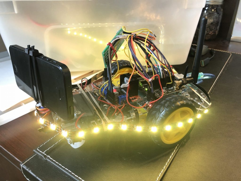
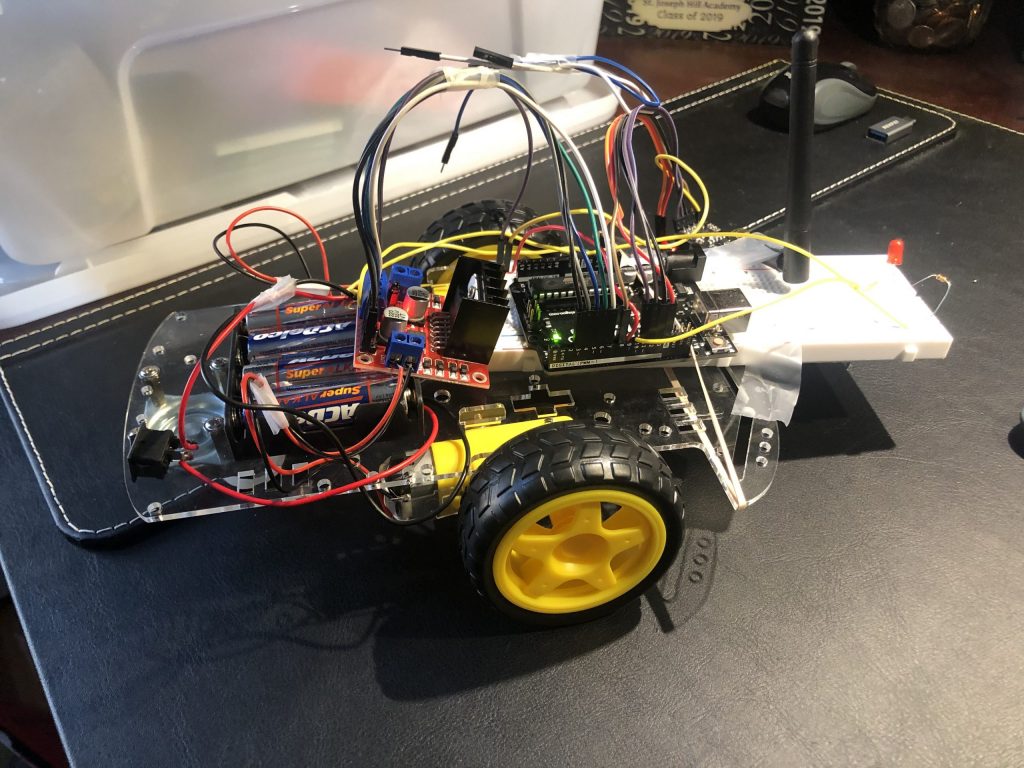
Pictures of Final Project
Third Milestone
#include <SPI.h>
#include <nRF24L01.h>
#include <RF24.h>
#include <Adafruit_MPU6050.h>
#include <Adafruit_Sensor.h>
#include <Wire.h>
#include <L298N.h>
const unsigned int IN1 = 7;
const unsigned int IN2 = 6;
const unsigned int ENA = 9;
const unsigned int IN3 = 5;
const unsigned int IN4 = 4;
const unsigned int ENB = 3;
RF24 radio(2, 8); // CE, CSN
int value = -1;
const byte address[6] = “00001”;
Adafruit_MPU6050 mpu;
void setup() {
Serial.begin(9600);
radio.begin();
radio.openReadingPipe(0, address);
radio.setPALevel(RF24_PA_MIN);
radio.startListening();
pinMode (IN1, OUTPUT);
pinMode (IN2, OUTPUT);
pinMode (IN3, OUTPUT);
pinMode (IN4, OUTPUT);
pinMode (ENA, OUTPUT);
pinMode (ENB, OUTPUT);
delay(100);
}
void loop() {
if (radio.available()) {
radio.read(&value, sizeof(value));
Serial.println(value);
if (value == 2) {
Serial.print(“hi”);
analogWrite(ENA, 255);
analogWrite(ENB, 255);
digitalWrite(IN1, HIGH);
digitalWrite(IN2, LOW);
digitalWrite(IN3, LOW);
digitalWrite(IN4, HIGH);
}
else if (value == 3) {
analogWrite(ENA, 255);
analogWrite(ENB, 255);
digitalWrite(IN1, LOW);
digitalWrite(IN2, HIGH);
digitalWrite(IN3, HIGH);
digitalWrite(IN4, LOW);
}
else if (value == 0) {
analogWrite(ENA, 255);
analogWrite(ENB, 255);
digitalWrite(IN1, LOW);
digitalWrite(IN2, HIGH);
digitalWrite(IN3, LOW);
digitalWrite(IN4, HIGH);
}
else if (value == 1) {
analogWrite(ENA, 255);
analogWrite(ENB, 255);
digitalWrite(IN1, HIGH);
digitalWrite(IN2, LOW);
digitalWrite(IN3, HIGH);
digitalWrite(IN4, LOW);
}
else if (value == 4) {
analogWrite(ENA, 0);
analogWrite(ENB, 0);
digitalWrite(IN1, LOW);
digitalWrite(IN2, LOW);
digitalWrite(IN3, LOW);
digitalWrite(IN4, LOW);
}
else {
analogWrite(ENA, 0);
analogWrite(ENB, 0);
digitalWrite(IN1, LOW);
digitalWrite(IN2, LOW);
digitalWrite(IN3, LOW);
digitalWrite(IN4, LOW);
//digitalWrite(10, LOW);
}
}
}
#include <SPI.h>
#include <nRF24L01.h>
#include <RF24.h>
#include <Adafruit_MPU6050.h>
#include <Adafruit_Sensor.h>
#include <Wire.h>
int command = -1;//0=foward
//1=backwards
//2=right
//3=left
RF24 radio(9, 8); // CE, CSN
const byte address[6] = “00001”;
Adafruit_MPU6050 mpu;
void setup() {
Serial.begin(115200);
while (!Serial)
delay(10); // will pause Zero, Leonardo, etc until serial console opens
Serial.println(“Adafruit MPU6050 test!”);
// Try to initialize!
if (!mpu.begin()) {
Serial.println(“Failed to find MPU6050 chip”);
while (1) {
delay(10);
}
}
Serial.println(“MPU6050 Found!”);
radio.begin();
radio.openWritingPipe(address);
radio.setPALevel(RF24_PA_MIN);
radio.stopListening();
mpu.setAccelerometerRange(MPU6050_RANGE_8_G);
Serial.print(“Accelerometer range set to: “);
switch (mpu.getAccelerometerRange()) {
case MPU6050_RANGE_2_G:
Serial.println(“+-2G”);
break;
case MPU6050_RANGE_4_G:
Serial.println(“+-4G”);
break;
case MPU6050_RANGE_8_G:
Serial.println(“+-8G”);
break;
case MPU6050_RANGE_16_G:
Serial.println(“+-16G”);
break;
}
mpu.setGyroRange(MPU6050_RANGE_500_DEG);
Serial.print(“Gyro range set to: “);
switch (mpu.getGyroRange()) {
case MPU6050_RANGE_250_DEG:
Serial.println(“+- 250 deg/s”);
break;
case MPU6050_RANGE_500_DEG:
Serial.println(“+- 500 deg/s”);
break;
case MPU6050_RANGE_1000_DEG:
Serial.println(“+- 1000 deg/s”);
break;
case MPU6050_RANGE_2000_DEG:
Serial.println(“+- 2000 deg/s”);
break;
}
mpu.setFilterBandwidth(MPU6050_BAND_21_HZ);
Serial.print(“Filter bandwidth set to: “);
switch (mpu.getFilterBandwidth()) {
case MPU6050_BAND_260_HZ:
Serial.println(“260 Hz”);
break;
case MPU6050_BAND_184_HZ:
Serial.println(“184 Hz”);
break;
case MPU6050_BAND_94_HZ:
Serial.println(“94 Hz”);
break;
case MPU6050_BAND_44_HZ:
Serial.println(“44 Hz”);
break;
case MPU6050_BAND_21_HZ:
Serial.println(“21 Hz”);
break;
case MPU6050_BAND_10_HZ:
Serial.println(“10 Hz”);
break;
case MPU6050_BAND_5_HZ:
Serial.println(“5 Hz”);
break;
}
Serial.println(“”);
delay(100);
}
void loop() {
sensors_event_t a, g, temp;
mpu.getEvent(&a, &g, &temp);
Serial.print(a.acceleration.x);
Serial.print(” “);
Serial.println(a.acceleration.y);
delay(250);
if (a.acceleration.x < -3) {
command = 2;
Serial.println(command);
radio.write(&command, sizeof(command));
}
else if (a.acceleration.x > 3) {
command = 3;
Serial.println(command);
radio.write(&command, sizeof(command));
}
else if (a.acceleration.y < -3) {
command = 0;
Serial.println(command);
radio.write(&command, sizeof(command));
}
else if (a.acceleration.y > 3) {
command = 1;
Serial.println(command);
radio.write(&command, sizeof(command));
}
else if (-3 < a.acceleration.y && a.acceleration.x < 3) {
command = 4;
Serial.println(command);
radio.write(&command, sizeof(command));
}
}
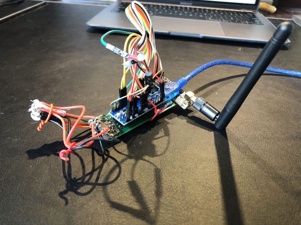
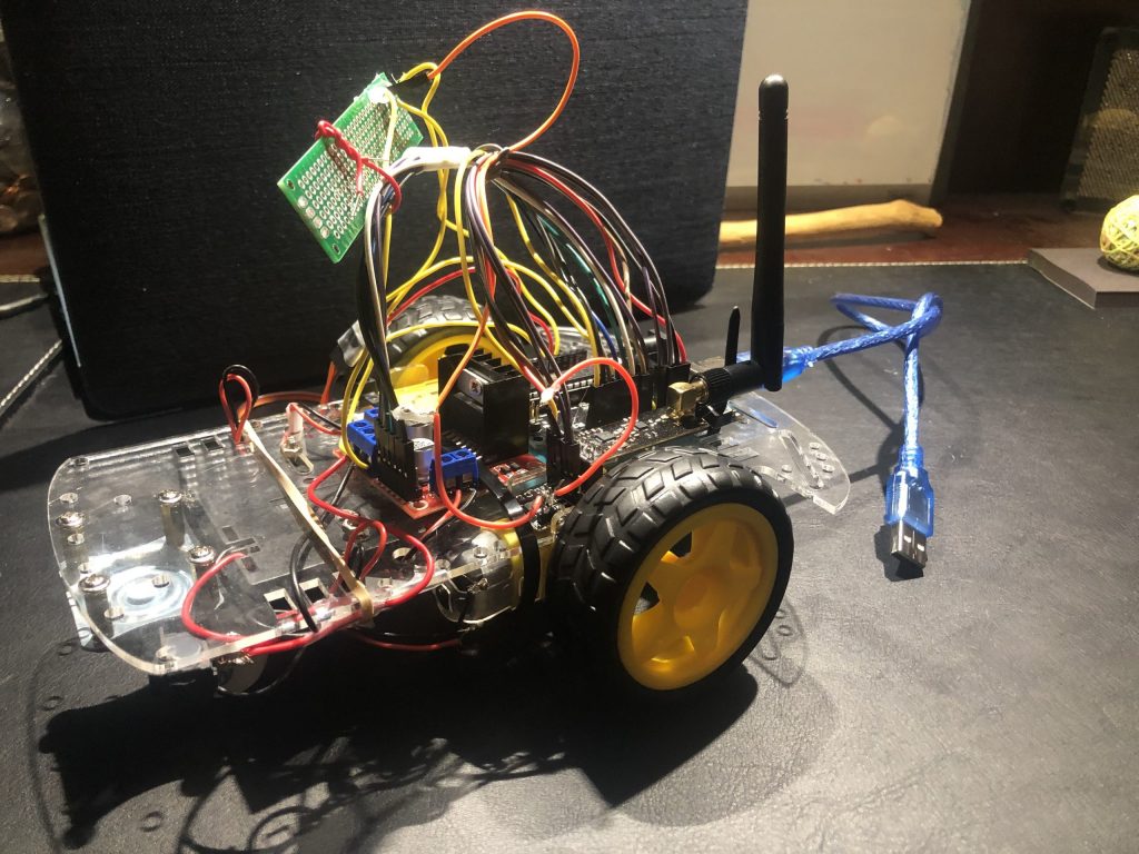
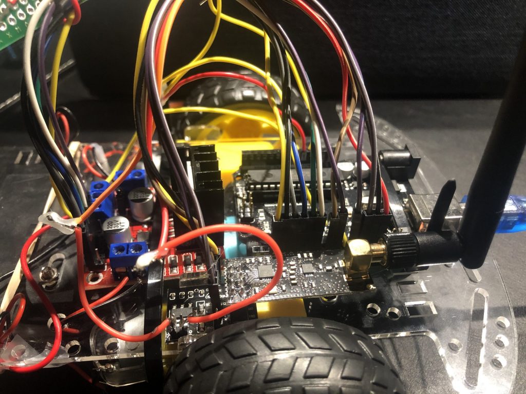
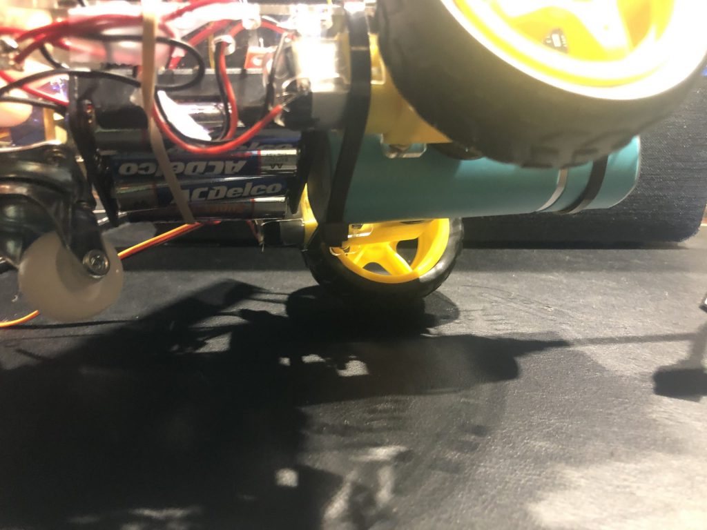
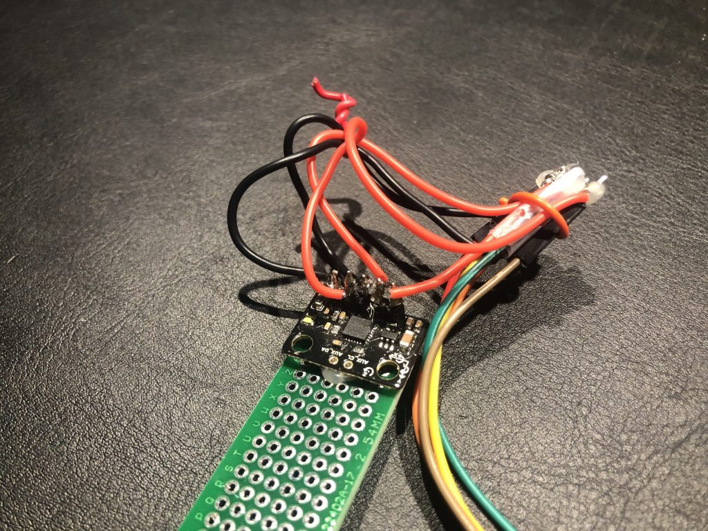
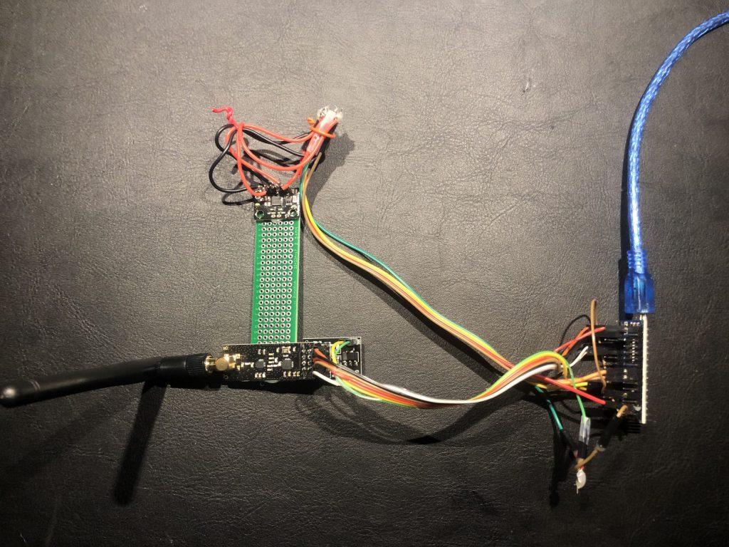
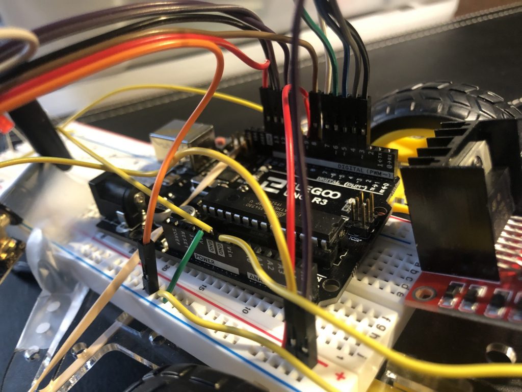
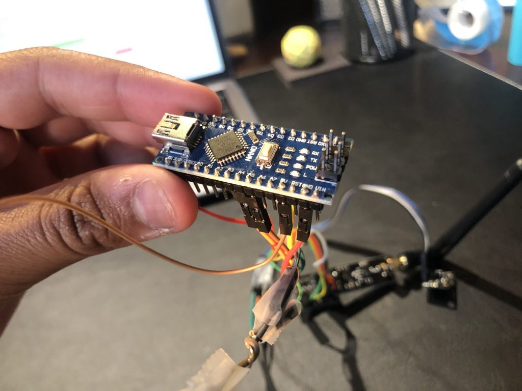
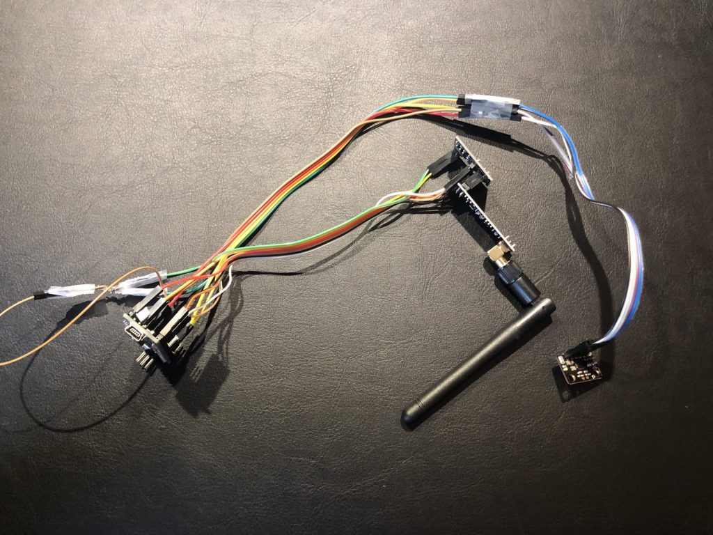
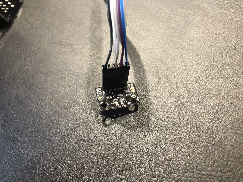
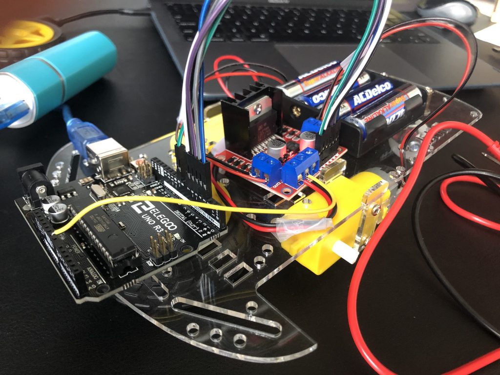
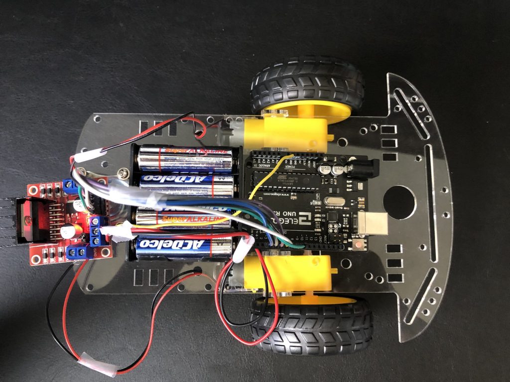
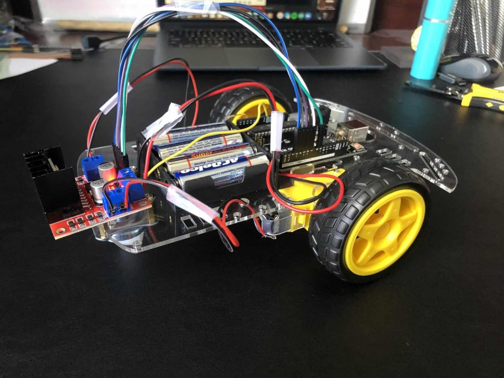
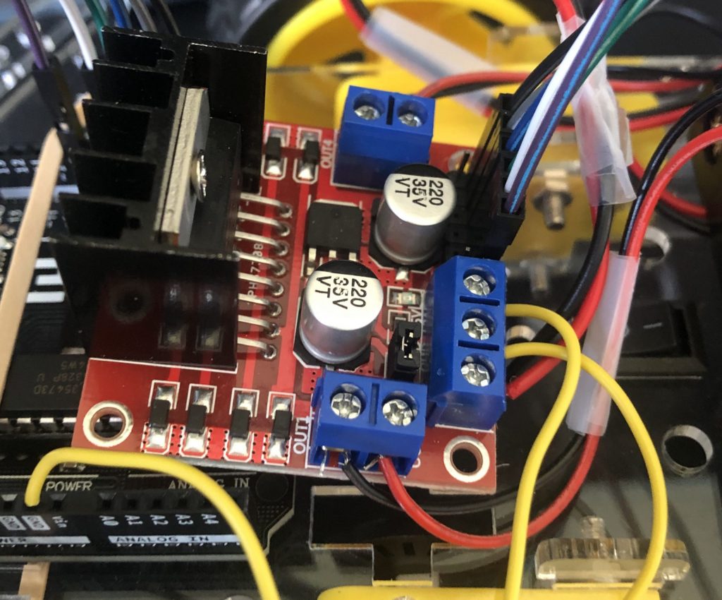
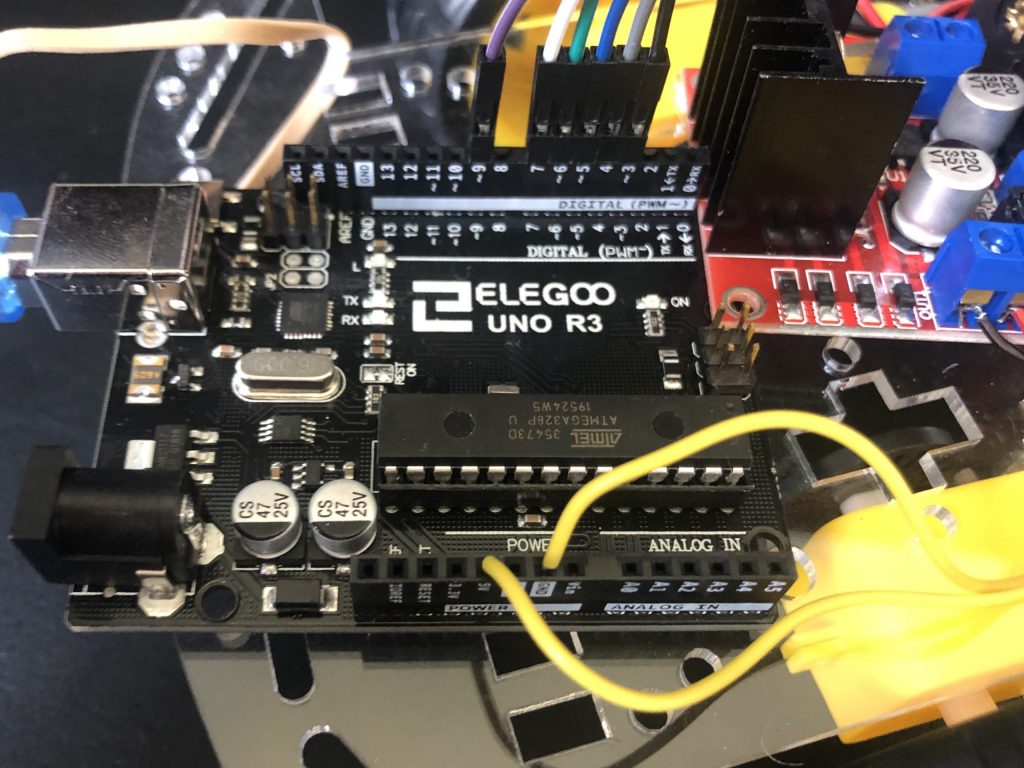
Along with this coding, I also did some soldering to ensure proper connections within all the circuits. I realized that the jumper wires on the accelerometer and some on one of the nRF modules were loose, therefore I decided to directly solder wires to each of the pins which was quite challenging. Due to the close proximity of the pins, it was difficult to place my soldering iron between the pins without getting solder on another pin and risk two pins being accidentally connected. I also soldered other minor wires that may have previously been twisted together. The 5 volt port on my Arduino had many wires connected to it, so I soldered them all to a perf board and added solder to connect the wires to ensure a strong connection. The main issue I came across during this milestone is that my nRF modules would not work consistently, and after much trial and error I found my problem. As mentioned before, some of the jumper wires were loose, specifically the power wires connected to one of the nRF modules. To fix this like I said I soldered wires directly to the pins. After finishing the base project, I organized my car and glove components. I attached all the power on the car to the underside of it and left the nRF module, motor driver, and Arduino on top. The Arduino, motor driver, and portable charger were all secured by zip ties. The battery pack was actually screwed to the base of the car. The wires floating about were bounded together using spare wire. On the glove portion of my project, I used a perf board as a base to attach the nRF module and accelerometer to. I intend on attaching the Arduino Nano as well. This is what I did to complete my third milestone.
Pictures of Car
Pictures of Glove Components
Second Milestone
#include <Adafruit_MPU6050.h>
#include <Adafruit_Sensor.h>
#include <Wire.h>
Adafruit_MPU6050 mpu;
const int IN1 = 7;
const int IN2 = 6;
const int IN3 = 5;
const int IN4 = 4;
const int ENA = 9;
const int ENB = 3;
int motorspeed=0;
void setup(void) {
Serial.begin(115200);
while (!Serial)
delay(10); // will pause Zero, Leonardo, etc until serial console opens
Serial.println(“Adafruit MPU6050 test!”);
// Try to initialize!
if (!mpu.begin()) {
Serial.println(“Failed to find MPU6050 chip”);
while (1) {
delay(10);
pinMode (IN1, OUTPUT);
pinMode (IN2, OUTPUT);
pinMode (IN3, OUTPUT);
pinMode (IN4, OUTPUT);
pinMode (ENA, OUTPUT);
pinMode (ENB, OUTPUT);
}
}
Serial.println(“MPU6050 Found!”);
mpu.setAccelerometerRange(MPU6050_RANGE_8_G);
Serial.print(“Accelerometer range set to: “);
switch (mpu.getAccelerometerRange()) {
case MPU6050_RANGE_2_G:
Serial.println(“+-2G”);
break;
case MPU6050_RANGE_4_G:
Serial.println(“+-4G”);
break;
case MPU6050_RANGE_8_G:
Serial.println(“+-8G”);
break;
case MPU6050_RANGE_16_G:
Serial.println(“+-16G”);
break;
}
mpu.setGyroRange(MPU6050_RANGE_500_DEG);
Serial.print(“Gyro range set to: “);
switch (mpu.getGyroRange()) {
case MPU6050_RANGE_250_DEG:
Serial.println(“+- 250 deg/s”);
break;
case MPU6050_RANGE_500_DEG:
Serial.println(“+- 500 deg/s”);
break;
case MPU6050_RANGE_1000_DEG:
Serial.println(“+- 1000 deg/s”);
break;
case MPU6050_RANGE_2000_DEG:
Serial.println(“+- 2000 deg/s”);
break;
}
mpu.setFilterBandwidth(MPU6050_BAND_21_HZ);
Serial.print(“Filter bandwidth set to: “);
switch (mpu.getFilterBandwidth()) {
case MPU6050_BAND_260_HZ:
Serial.println(“260 Hz”);
break;
case MPU6050_BAND_184_HZ:
Serial.println(“184 Hz”);
break;
case MPU6050_BAND_94_HZ:
Serial.println(“94 Hz”);
break;
case MPU6050_BAND_44_HZ:
Serial.println(“44 Hz”);
break;
case MPU6050_BAND_21_HZ:
Serial.println(“21 Hz”);
break;
case MPU6050_BAND_10_HZ:
Serial.println(“10 Hz”);
break;
case MPU6050_BAND_5_HZ:
Serial.println(“5 Hz”);
break;
}
Serial.println(“”);
delay(100);
}
void loop() {
/* Get new sensor events with the readings */
sensors_event_t a, g, temp;
mpu.getEvent(&a, &g, &temp);
/* Print out the values */
Serial.print(“Acceleration X: “);
Serial.print(a.acceleration.x);
motorspeed=map(a.acceleration.x, -10, 10, 0, 255);
if (a.acceleration.x<2 && a.acceleration.x>-2) {
analogWrite(ENA, 255);
analogWrite(ENB, 255);
digitalWrite(IN1, LOW);
digitalWrite(IN2, LOW);
digitalWrite(IN3, LOW);
digitalWrite(IN4, LOW);
}
else{
analogWrite(ENA, motorspeed);
analogWrite(ENB, motorspeed);
digitalWrite(IN1, HIGH);
digitalWrite(IN2, LOW);
digitalWrite(IN3, HIGH);
digitalWrite(IN4, LOW);
}
Serial.print(“, Y: “);
Serial.print(a.acceleration.y);
if (a.acceleration.y>2) {
digitalWrite(IN1, HIGH);
digitalWrite(IN2, LOW);
digitalWrite(IN3, LOW);
digitalWrite(IN4, LOW);
}
Serial.print(“, Z: “);
Serial.print(a.acceleration.z);
Serial.println(” m/s^2″);
Serial.print(“Rotation X: “);
Serial.print(g.gyro.x);
Serial.print(“, Y: “);
Serial.print(g.gyro.y);
Serial.print(“, Z: “);
Serial.print(g.gyro.z);
Serial.println(” rad/s”);
Serial.print(“Temperature: “);
Serial.print(temp.temperature);
Serial.println(” degC”);
Serial.println(“”);
delay(500);
}
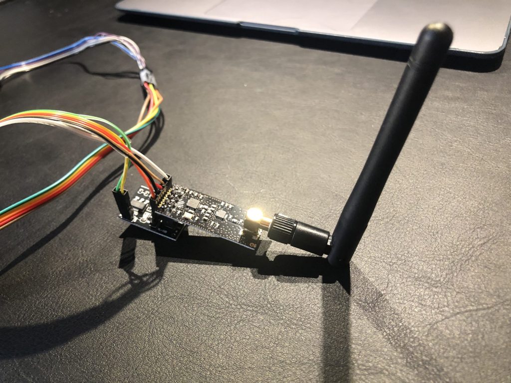
After doing all of these tests on the accelerometer, I then focused on the nRF modules. The nRF modules were very difficult to get to work, but after establishing the initial connection they seemed to then work consistently. After three days of switching pins around, checking all connections, and finding and modifying different code, I was able to get the modules to communicate with each other. That was my big problem in milestone 2, due to the complex nature of the modules and the time it took to work. The code I used to get the modules working sent a simple message “Hello World.” In the code the only things I really changed were that I used different ports for the CE and CSN connections. After getting words to be sent through the nRF modules, I decided that the next step was to get integers to be sent. To do this I used the “int” function, because using this function allows numbers, more specifically integers to be sent between modules.
#include <SPI.h>
#include <nRF24L01.h>
#include <RF24.h>
RF24 radio(2, 8); // CE, CSN
const byte address[6] = “00001”;
void setup() {
Serial.begin(9600);
radio.begin();
radio.openReadingPipe(0, address);
radio.setPALevel(RF24_PA_MIN);
radio.startListening();
}
void loop() {
if (radio.available()) {
char text[32] = “”;
radio.read(&text, sizeof(text));
Serial.println(text);
}
}
#include <SPI.h>
#include <nRF24L01.h>
#include <RF24.h>
RF24 radio(9, 8); // CE, CSN
const byte address[6] = “00001”;
void setup() {
radio.begin();
radio.openWritingPipe(address);
radio.setPALevel(RF24_PA_MIN);
radio.stopListening();
}
void loop() {
const char text[] = “Hello World”;
radio.write(&text, sizeof(text));
delay(1000);
}
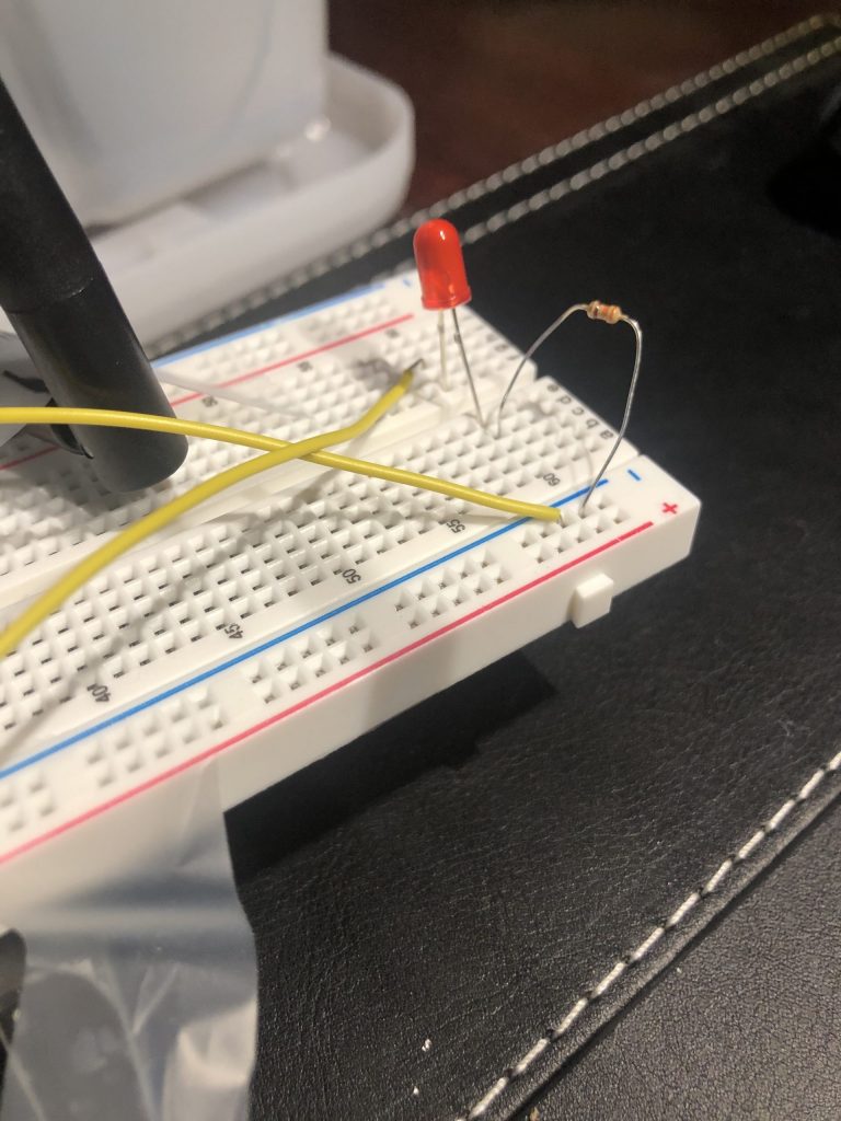
After learning extensively about the accelerometer and nRF modules, I decided to finally combine them and send accelerometer values through the nRF modules. I first changed the nRF code to be able to send and receive decimals, because the accelerometer is quite precise and does not just send integers. To do this, I used the “float” function. This task was not very easy and a lot of code had to be changed to send the decimal values, but once I did so, the rest was easier. In order to see if the proper values were printing and to watch the values change I used the “serial print” function to print the values that the receiver was reading. In order to see these values, the Arduino would have to be plugged into my computer and the serial monitor would have to be opened too. Next, I connected a LED to the Arduino Uno and decided I wanted to use what I learned to turn on a LED using accelerometer values with the use of nRF modules. To do so I wrote an “if” statement in the receiver’s code to say that if the value is above a certain value, turn the LED on and used an “else” statement to say if not, turn the LED off. I wirelessly turned a LED on through the tilting of the accelerometer. This is what I did to complete my second milestone.
#include <SPI.h>
#include <nRF24L01.h>
#include <RF24.h>
#include <Adafruit_MPU6050.h>
#include <Adafruit_Sensor.h>
#include <Wire.h>
RF24 radio(2, 8); // CE, CSN
const byte address[6] = “00001”;
Adafruit_MPU6050 mpu;
void setup() {
Serial.begin(9600);
radio.begin();
radio.openReadingPipe(0, address);
radio.setPALevel(RF24_PA_MIN);
radio.startListening();
pinMode(10, OUTPUT);
delay(100);
}
void loop() {
float value;
if (radio.available()) {
radio.read(&value, 4);
Serial.println(value);
if (value > 3) {
digitalWrite(10, HIGH);
}
else {
digitalWrite(10, LOW);
}
}
}
#include <SPI.h>
#include <nRF24L01.h>
#include <RF24.h>
#include <Adafruit_MPU6050.h>
#include <Adafruit_Sensor.h>
#include <Wire.h>
RF24 radio(9, 8); // CE, CSN
const byte address[6] = “00001”;
Adafruit_MPU6050 mpu;
void setup() {
Serial.begin(115200);
while (!Serial)
delay(10); // will pause Zero, Leonardo, etc until serial console opens
Serial.println(“Adafruit MPU6050 test!”);
// Try to initialize!
if (!mpu.begin()) {
Serial.println(“Failed to find MPU6050 chip”);
while (1) {
delay(10);
}
}
Serial.println(“MPU6050 Found!”);
radio.begin();
radio.openWritingPipe(address);
radio.setPALevel(RF24_PA_MIN);
radio.stopListening();
mpu.setAccelerometerRange(MPU6050_RANGE_8_G);
Serial.print(“Accelerometer range set to: “);
switch (mpu.getAccelerometerRange()) {
case MPU6050_RANGE_2_G:
Serial.println(“+-2G”);
break;
case MPU6050_RANGE_4_G:
Serial.println(“+-4G”);
break;
case MPU6050_RANGE_8_G:
Serial.println(“+-8G”);
break;
case MPU6050_RANGE_16_G:
Serial.println(“+-16G”);
break;
}
mpu.setGyroRange(MPU6050_RANGE_500_DEG);
Serial.print(“Gyro range set to: “);
switch (mpu.getGyroRange()) {
case MPU6050_RANGE_250_DEG:
Serial.println(“+- 250 deg/s”);
break;
case MPU6050_RANGE_500_DEG:
Serial.println(“+- 500 deg/s”);
break;
case MPU6050_RANGE_1000_DEG:
Serial.println(“+- 1000 deg/s”);
break;
case MPU6050_RANGE_2000_DEG:
Serial.println(“+- 2000 deg/s”);
break;
}
mpu.setFilterBandwidth(MPU6050_BAND_21_HZ);
Serial.print(“Filter bandwidth set to: “);
switch (mpu.getFilterBandwidth()) {
case MPU6050_BAND_260_HZ:
Serial.println(“260 Hz”);
break;
case MPU6050_BAND_184_HZ:
Serial.println(“184 Hz”);
break;
case MPU6050_BAND_94_HZ:
Serial.println(“94 Hz”);
break;
case MPU6050_BAND_44_HZ:
Serial.println(“44 Hz”);
break;
case MPU6050_BAND_21_HZ:
Serial.println(“21 Hz”);
break;
case MPU6050_BAND_10_HZ:
Serial.println(“10 Hz”);
break;
case MPU6050_BAND_5_HZ:
Serial.println(“5 Hz”);
break;
}
Serial.println(“”);
delay(100);
}
void loop() {
sensors_event_t a, g, temp;
mpu.getEvent(&a, &g, &temp);
Serial.println(a.acceleration.x);
radio.write(&a.acceleration.x,4);
delay(1000);
}
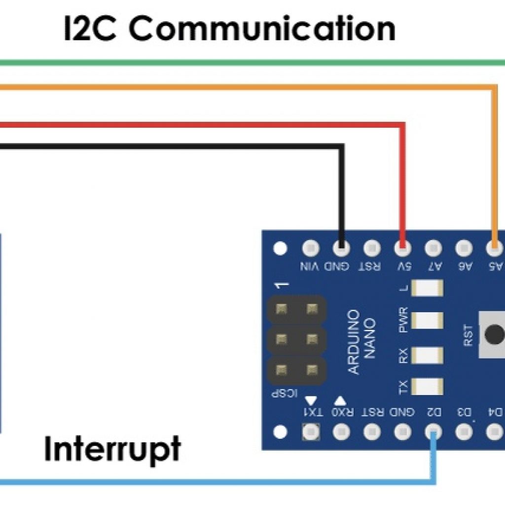
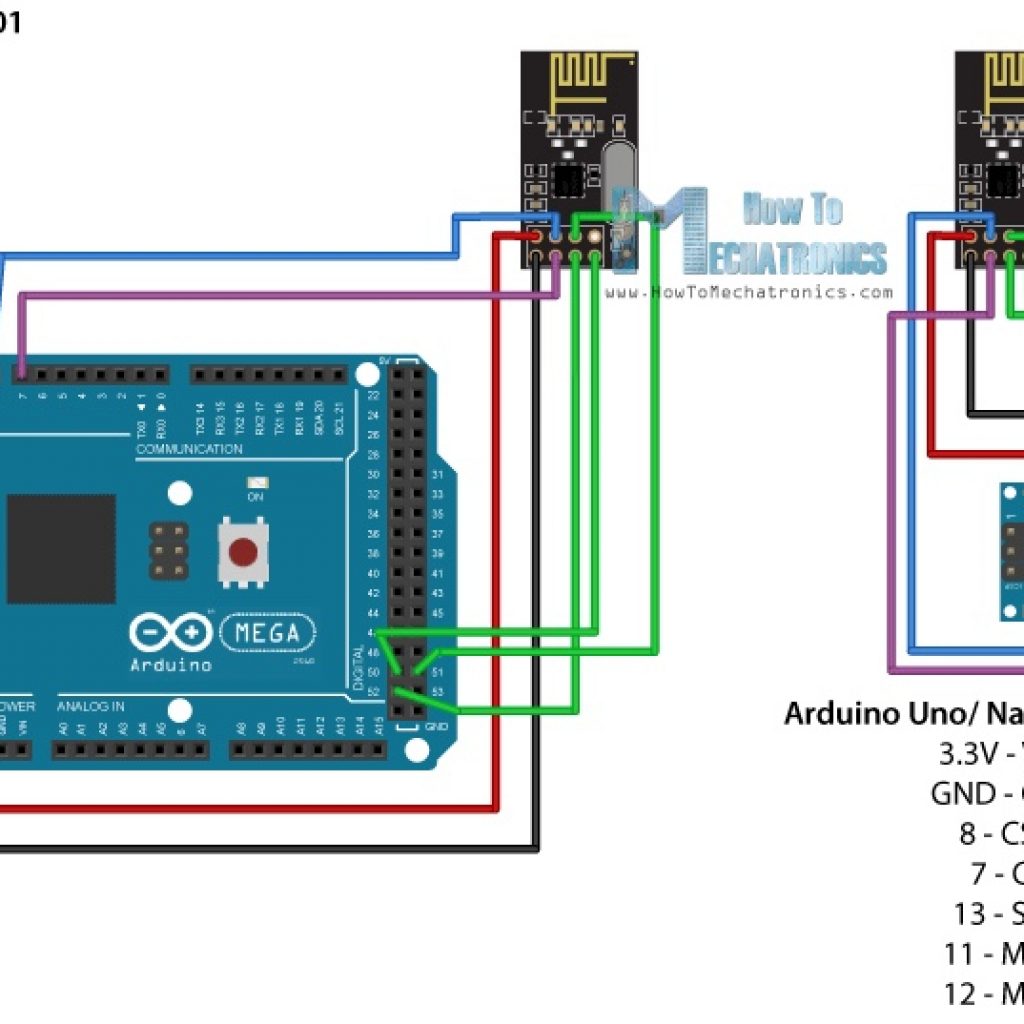
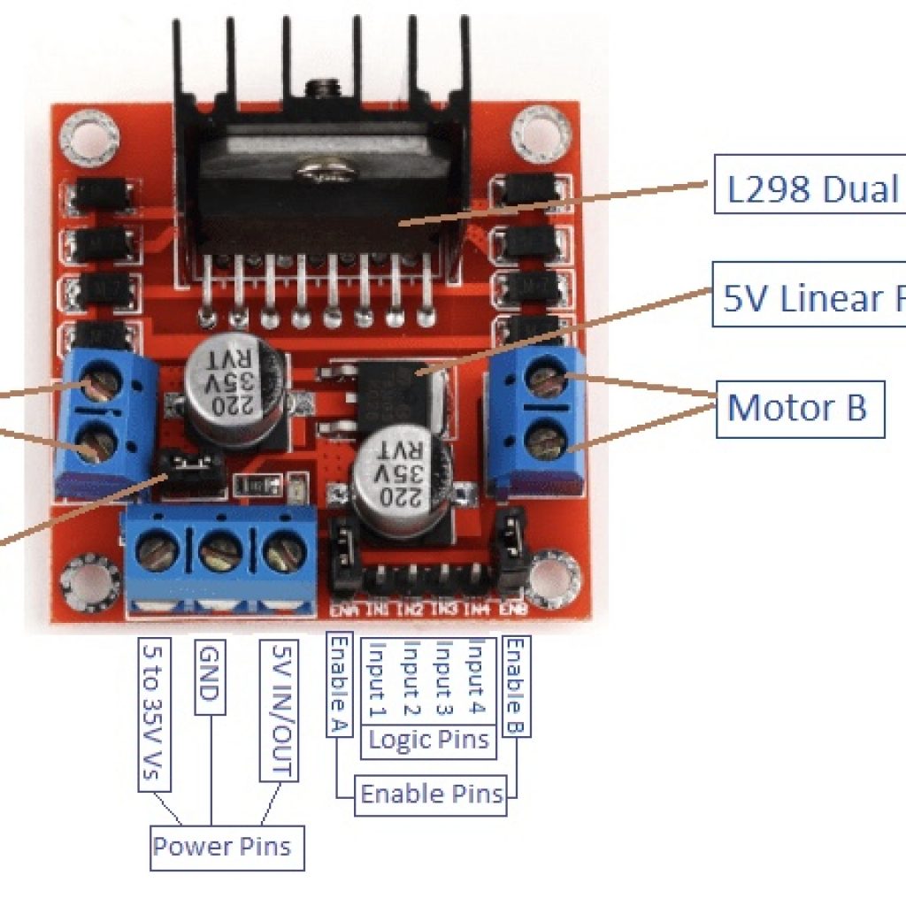
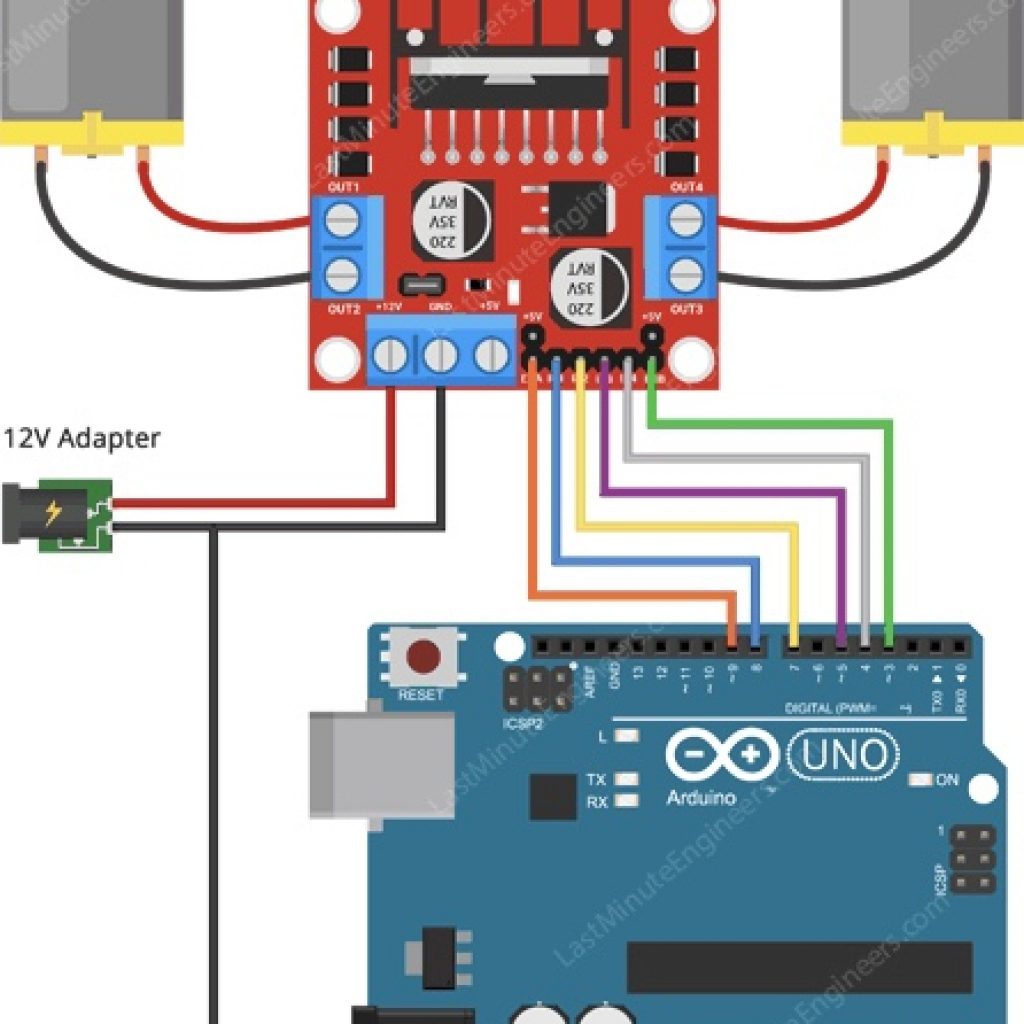
Diagrams of Circuit Connections
Pictures of Car
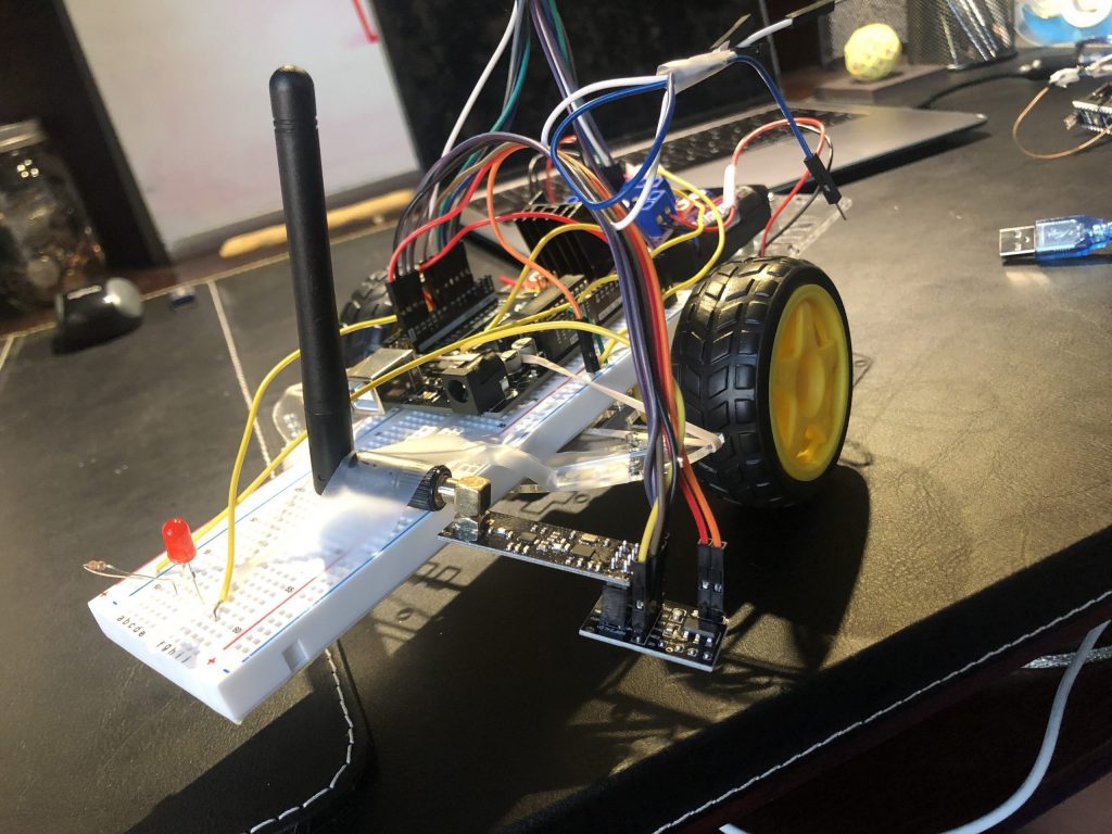
Pictures of Glove Components
First Milestone
#include <L298N.h>
// Pin definition
const unsigned int IN1 = 7;
const unsigned int IN2 = 6;
const unsigned int ENA = 9;
const unsigned int IN3 = 5;
const unsigned int IN4 = 4;
const unsigned int ENB = 3;
// Create one motor instance
L298N motor(ENA, IN1, IN2);
L298N motor2(ENB, IN3, IN4);
void setup()
{
// Used to display information
Serial.begin(9600);
// Wait for Serial Monitor to be opened
while (!Serial)
{
//do nothing
}
// Set initial speed
motor.setSpeed(70);
motor2.setSpeed(70);
}
void loop()
{
// Tell the motor to go forward (may depend by your wiring)
motor.forward();
motor2.forward();
// Alternative method:
// motor.run(L298N::FORWARD);
//print the motor satus in the serial monitor
printSomeInfo();
delay(3000);
// Stop
motor.stop();
motor2.stop();
// Alternative method:
// motor.run(L298N::STOP);
printSomeInfo();
// Change speed
motor.setSpeed(255);
motor2.setSpeed(255);
delay(3000);
// Tell the motor to go back (may depend by your wiring)
motor.backward();
motor2.backward();
// Alternative method:
// motor.run(L298N::BACKWARD);
printSomeInfo();
motor.setSpeed(120);
motor2.setSpeed(120);
delay(3000);
// Stop
motor.stop();
motor2.stop();
printSomeInfo();
delay(3000);
}
/*
Print some informations in Serial Monitor
*/
void printSomeInfo()
{
Serial.print(“Motor is moving = “);
Serial.print(“Motor2 is moving = “);
Serial.print(motor.isMoving());
Serial.print(motor2.isMoving());
Serial.print(” at speed = “);
Serial.print(” at speed = “);
Serial.println(motor.getSpeed());
Serial.println(motor2.getSpeed());
}
Diagrams of Circuit Connections
Pictures of Car
Parts List For Main Project:
(1)Arduino Uno
(1)Arduino Nano
(1)Car Base
(1)Accelerometer(MPU 6050)
(2)nRF Modules
(2)DC Motors
(2)Rubber Wheels
(1)Motor Driver(L298N)
(1)6 Volt Battery Pack
(2)Portable Chargers
(1)Switch
(2)Perfboards
(Many)Jumper Wires