Introduction
Hey, I’m Skylar. I’m a rising sophomore at the Urban School of San Francisco. BlueStamp visited my school and gave presentation on their summer program. I was immediately interested, and I hope coming out of BlueStamp I will have the necessary tools for success. I have always been interested in how things work, and I assume that engineering is in my future.
Final Video
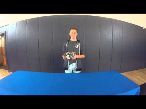

My final project is a tabletop robot – a small robot that roams around a surface but does not fall off once it approaches an edge. The chassis is built out of laser cut acrylic and assembled using screws and nuts. There are two continuous rotation servos for the motors, and two IR (infrared) sensor modules for the edge detection. In my code, the values that the modules create and give to the Arduino are what control how the servos move and henceforth making the robot back up when it reaches an edge. The challenges I faced while working on this project, such as the scaling of the chassis and learning how to code for the first time, gave me the opportunity to more deeply understand these concepts from the many hours I spent trying to figure them out.
Second Milestone: Sensors and Code
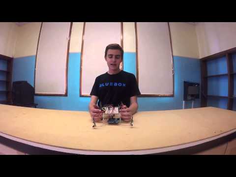
My second milestone goal was to complete the code for my Arduino, and to connect and make my sensors work. Being my first coding experience, learning how to program in Arduino was by far the most challenging part of the process. I was able to finally get my sensors to function properly, however the process took quite a long time. It required many trials of tuning and reading the sensors with the Arduino. The way my code works is that, when the sensor receives an infrared signal that its adjacent infrared LED emits (38 kHz), the Arduino reads a 1. When is does not receive a signal, it reads a 0. Depending on these values, the servos (motors), complete certain series of motions through a series of if statements in the code.
First Milestone: Chassis and Servos
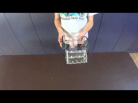
For my main project, I am making a tabletop robot. It can roll around a surface, and when it approaches an edge it will back away. I chose this project because I wanted to gain experience in the two areas of hardware and software, rather than just one. My robot involved quite a few challenges in terms of constructing the body, such as scaling the design for laser cutting, attaching the wheels to the servo motors, and fitting the nuts into their corresponding pockets. I originally had a design on Adobe Illustrator that I had laser cut, however it was scaled incorrectly meaning all of my pieces were 20% too big and none of my other parts would work. To fix this, the design had to be scaled down to the correct size to work with our sheet of acrylic.
My Tabletop Robot Arduino Code, Schematics, and Bill of Materials:
Here is my Bill of Materials for the tabletop robot.
Here is the github for my Arduino code.

Starter Project
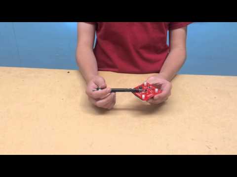
For my starter project, I built a simon says game. There was quite a lot of soldering involved in constructing the circuit board, and the majority was surface mounted. Surface mounts are small metal pads that lie flush with the board, and components are soldered while resting on top of them rather than pins that are soldered on the other side of the board. This was a significant challenge as I had never had any soldering experience before. The way the game works is that electricity flows from the power source (in this case a battery) and passes through several capacitors and resistors to control and modify the current before it reaches the microcontroller. The capacitors serve as extra power storage in case the voltage decreases – if the voltage decreases, even just for a second, the microcontroller will restart and so will the game. Resistors are devices that limit and regulate the current in the circuit so the microcontroller and buzzer receive the proper amount of electricity to function. Once electricity reaches the microcontroller, it starts the game. When a button is pressed, a circuit is closed – when the microcontroller detects this new current, it gives electricity to the corresponding LED to light up and to the buzzer which generates an audio response.
this project is very creative i like it