
Piano for the Hearing Impaired
For my intensive project, I decided to create a Student Defined Project. I’m passionate about music and social good, so I knew I wanted to incorporate those concepts into my project somehow. I wrestled with a couple of ideas, and decided on building a piano for people who are Hard of Hearing. In a sense, I wanted to build a machine that would have more tactile stimulation and also translate music into a visual display.
Engineer
Sira N.
Area of Interest
Jazz Composition/ Mechanical Engineering
School
Trinity School
Grade
Incoming Senior
Final Milestone: Building a Frame and Visual Modifications
My final milestone was building a frame for my piano and working on the visualization with Processing. Originally, I had a small toy piano that would serve as the base for my actual piano, but the FSRs were too large to fit on the keys. Instead, Sam and Jessie suggested I build a piano from scratch. First I sketched out a build plan for the piano. I knew I would need a frame to accommodate twelve 1″ wide keys, and some allowance for space in between them. I also knew I wanted two layers of keys, one layer for naturals and one for accidentals. I also needed springs to attach underneath each key so there would be some resistance when the user pressed on the keys so the FSRs could read the force values accurately.

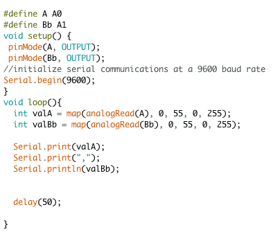
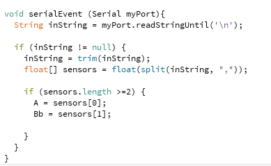
In Arduino, I coded 12 keys, but for simplicity I’ll be describing the setup of just two keys. This code is pretty much identical to my Milestone 1 code, save for what’s being printed into the Serial monitor. In between each FSR value of the individual keys, I’m printing a comma. The final value I want Processing to receive, in this case it’s ‘valBb,’ must used a Serial.println() function, so that each set of values is printed on a new line while the loop runs. This will come into play later with the Processing code. I also added a delay function at the end of the loop as a method of not sending too much information at once to Processing.
After I verified my build plan with Sam and Jessie and got some wood, I began cutting the wood into the pieces I wanted. I had a long 3/4″ thick plank of wood that I cut into twelve 1″ wide pieces and used for the keys. I also had four 1/2″ thick wood planks that I used as the frame for the piano, and cut two 4″ pieces and one 15″ piece. Jessie and Sam got me this long zinc coated dowel, which I would used to align the two layers of keys. To do this, I sliced my dowel in half, and then drilled holes through the sides of my keys. I stuck each half of the dowels through the keys, 7 for the bottom layer and 5 for the top layer, and arranged them the same way as a typical piano. I super glued the keys in place so they wouldn’t move around, and glued their respective springs underneath them. I then glued each FSR and micro vibration motor to its corresponding key, and glued the breadboard to the back of the piano to keep everything in place.
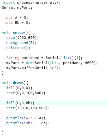
As for the visual modifications, I ended up heavily modifying the visuals after recording my final milestone video. As for individual keys, I altered the code to display a randomly generated ellipses that corresponded to a certain color. For example, if the user presses on the C key, red ellipses will be displayed in the column. The size and transparency of these ellipses is dependent on the FSR value, so if the user presses hard, the ellipses are more opaque and larger. The reverse is true if the user presses softly. If the user presses two keys that are not in a chord, these ellipses can overlap and create a cool pseudo color mixing visual.
However, if the user presses three keys that are in a chord, a different visual will be displayed. I create a gradient adjacent visual that is dependent on the frequencies of the notes in the chord. I have four possible variations of chords coded: major, minor, diminished, and power chords. The visuals are mostly dependent on the third of the chord, since that is the most defining part of the quality of a chord. For example, a major chord, which has a major third, displays a bright and vibrant visual, while a minor chord, which contains a minor third, has a duller and less saturated visual. Diminished chords incorporate the flat fifth of the chord, so that visual is even more dull to mimic the chord quality. Power chords only have the root and the fifth, so while it is vibrant and saturated, it is not as bright as a typical major chord. In the video, I play individual notes and then demonstrate the iterations of the C chord. In order, I play a C major, a C minor, a C diminished, and a C power chord.
Second Milestone: Visual Component
My second milestone is the visual component of the piano. My vision is that each key will have its own color, and the saturation of that color will be dependent on how hard the user presses the FSR. I also plan to have chords have some sort of visual indication of there quality. For example, a major chord produces a bright or happy sound, and that would be reflected in the brightness of the color displayed on screen. A minor chord produces a muddier, darker sound, and that again would be represented by a darker/duller color on screen. Because the piano has 12 keys, it’s hard to play 7th, 9th, or 13th chords effectively, but I hope to have a range of visuals respective to possible chord qualities achieved with three notes.
My second milestone is the visual component of the piano. My vision is that each key will have its own color, and the saturation of that color will be dependent on how hard the user presses the FSR. I also plan to have chords have some sort of visual indication of there quality. For example, a major chord produces a bright or happy sound, and that would be reflected in the brightness of the color displayed on screen. A minor chord produces a muddier, darker sound, and that again would be represented by a darker/duller color on screen. Because the piano has 12 keys, it’s hard to play 7th, 9th, or 13th chords effectively, but I hope to have a range of visuals respective to possible chord qualities achieved with three notes.
Arduino Code
First Milestone: Physical Components
My intensive project is piano designed for people with either complete or partial hearing loss. The piano has two components that appeal to touch and visual senses. The first component concerns vibration motors with Force Resisting Sensors (FSR). The second part will be an app that registers the keys the user presses and converts these readings into a visual display that uses colors and shapes to convey the visual meaning of the music being played.
My first milestone is the touch component of the piano. I used FSRs, micro vibration motors, and a lot of jumper cables to achieve the functionality I wanted.
Milestone 1
There are 12 FSRs used to represent the 12 notes in an octave, A through G#/Ab. The FSRs are connected to the analog pins of the Arduino Mega, allowing them to register varying levels of pressure. I connected each FSR to their respective clinchers, making it easier to connect to the breadboard using Male/Female jumper cables. I then connected each FSR to an individual analog pin, and placed a resistor right beneath where that connection was being made. I also connected each FSR to the positive well of the breadboard to pass a current through them. I arranged the FSRs to vaguely replicate a piano set up, and went on to work on the micro vibration motors.
I used a separate half-sized breadboard to connect the vibration motors to the Arduino. I used 12 to correspond with the 12 keys on the piano/the 12 FSRs. I connected the blue wires of the vibration motors to the ground well of the breadboard, and used jumper cables to connect the other end of the wire to the Arduino. I connected each motor to a digital pin on the Arduino, which would later receive an analog value to output in my Arduino code.
The code for this setup is a little busy, but that’s mostly by virtue of there being 12 keys to account for. I’ll walk through the setup of the ‘A’ key, but the setup for the other 11 keys is exactly the same.

Each key requires three variables unique to that key. One analog variable for the FSR pin, one digital pin for the vibration motor, and another to store the FSR reading. Three variables that are not unique to individual keys are the motorMap, forceMap, and scalar integer variables. The first two are used for the map function unique to each key, while the scalar is used to manipulate the FSR reading and increase sensitivity. This helps the vibration motors accurately communicate with the FSR in a way that’s realistic and parallels the actual force applied to the piano.
In my setup, I simply have the ‘A’ and ‘Av’ variables set as output pins.
In my loop, I first manipulate the FSR reading and scale it for the reasons mentioned above. I then created a variable named ‘valA,’ where I would store my mapped valued. The scales for an FSR and vibration motor are different, so I needed to use the map function to scale the FSR reading appropriately so they would correspond with values typically applied to a micro vibration motor.
I then used the analogWrite function to write the newly scaled value from the FSR to the ‘Av’ value, which is hooked up to the vibration motor. This makes it so that the force applied to the FSR is represented in how hard to motor vibrates. I then have some serial outputs for debugging purposes.
Starter Project
The Useless Machine is a box with a motor controlled arm inside. When the user flips the switch, the arm comes out of the box and flips the switch back to the original position. The net gain is 0, making the functionality of the machine useless. This project solidified my soldering abilities, as well as how to go about assembling all the pieces in a logical way, both in terms of functionality and position.
Components
How it works
The Useless Machine is powered by three triple 1.5V batteries. There is PCB circuit connecting all the parts of the machine, and it has two resistors, a flip switch, a snap switch, a 3 pin LED, and the wires of the motor attached. Attached to the motor is the acrylic arm, that will eventually flip the main switch that protrudes from the machine. When the user flips the switch, it closes the circuits in the PCB, allowing current to flow through all the components of the machine. Immediately, a green light from the LED is emitted, and the motor moves in one direction, allowing the arm to come out of the compartment and reach the switch. The motor is polar, so when the arm eventually flips the switch back into its original position, the motor starts to move in the opposite direction, bringing the arm back down. In addition, the LED emits a red light. Since the LED has two pins, it is able to emit two colors depending on where the current is being transferred to. When the switch is flipped back by the arm, the current is being transferred to the third LED pin, allowing red light to emit. When the arm goes back into the machine, a snap switch is directly beside it, and when the arm presses on it it signals the motor to stop moving, essentially turning the machine off.
Useless Machine Schematic
