After my Bluestamp experience I have began working on my project independently, as you can see by the picture I have gotten rid of that block on wood, and replaced both servo motors. In an update video, that I will be posting in a couple days you can see that I have the claw and the wheels working, my next step, of course, is to get the arm claw and wheels all working. Other future modifications I plan on making is adding faster motors, so my robot moves faster, and adding better wheels, hopefully made out of rubber. I found out that the mapping numbers on my robot were all messed up, and needed to be changed so they matched my mapping numbers that my flex sensors let out. I posted this mapping number test I used, and it worked fairly well, using it is easy as it states the flex sensor name, and value for me. Once I have my arm working I believe blacking it out would give it a pretty awesome look. Stay tuned for future updates/videos.
MY CODE CAN BE FOUND AT THE FOLLOWING LINK:
https://docs.google.com/document/d/1r1VQ7ZJ3Uyx4_Quf5kYepTnp9TEwRxh3qwmZ-R1DV8M/edit?usp=sharing


About Me


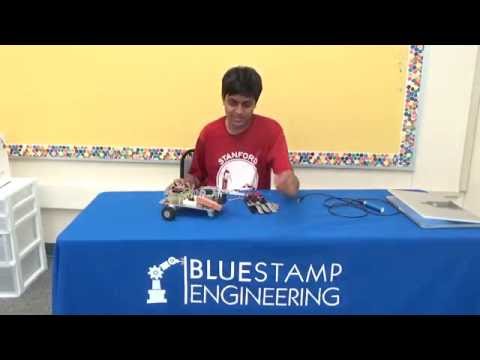
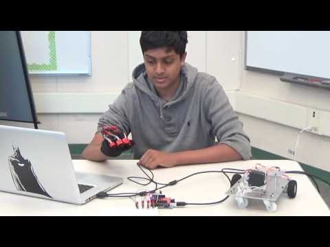
Hello, my name is Shaan, and I go to Mountain View High School. My main project is to create a hand gesture controlled robot, with a robotic arm. I used this website as a guide for my project. I have always been interested in raspberry pi, as they are inexpensive, and the projects you can create with them are abundant. I decided to do this project as it used Arduino, something that I have never seen, nor used before, and XBee. I thought that this project would be a great learning experience for me, and teach me more about software, electrical, and mechanical engineering. I really enjoyed the mechanical and electrical parts of my project, and found out that software was not for me. Although this project brought great frustration I was able to learn a lot. At Bluestamp you are put in a position where you are given help, but not the direct answer to the problem. You are forced to go out there and try new things, and do independent research, not only does this increase your researching skills, but it allows to problem solve without relaying on more experienced people. I really loved the way this camp was taught, most camps I have been to the instructors practically do the project for you, but here at Blustamp, I can truly call this project my own.
 

My Final Milestone

Shaan P – Final Milestone
For my final milestone I have my robots DC motors working. I ended up finding out that the Servo motors on my claw where not functional, and I need to purchase new Servos, but once I have my new servos, the software is all there and is as simple as plugging them into my breadboard. As you can see on my project I have a breadboard located on the middle on my robot. This breadboard is the home of the H-Bridge, which although took a couple days to get working, is not that hard to assemble. I ended up finding out that a 9V power supply along with the Arduino is enough for the HBridge to move the motors, and the two Servo Motors. Once I had the HBridge installed all I had to do was connect wire the HBridge by connecting everything in its proper socket. Looking at the picture below I have provided is a huge help,if you’re struggling with your HBridge. Lastly I wired my 60RPM DC motors, checked to make sure my wiring was functional, and attached them to my robot. As you can see by my code, it just adds motor code to my milestone two code. I learned a lot from my Bluestamp experience, and I cannot wait until I can start working on my project this summer, I will be posting on my page updates on how my project is going throughout the year.
 

My Second Milestone

Shaan P – Milestone #2
 

For my second milestone for my project was to get my glove to turn on LED lights wirelessly. Using XBees I am able to send information from my gloves arduino to my breadboards arduino. I used the same schematic that I used for my first milestone but instead of connecting to a breadboard I soldered them. After I soldered the flex sensors I shrink wrapped the flex sensors to make it look a better, and connected it to my arduino. I did a simple flex sensor test to see if they all still worked and everything ended up working. After the flex sensors were attached to the glove I started working on the XBees. I ended up having to go on Arduinos forum to find out some of my mistakes I had made, I found out that on my Arduino they were on the “UART” setting instead of “DLINE”. The XBees will not work with the Arduinos unless they are set to “DLINE” on the XBee Shield. Configuring the XBees were easier than I thought with the new XBee software, so getting them to communicate was pretty easy. Lastly, I built a simple LED breadboard using the schematic from the first milestone, then developed code that would turn on LED lights when the XBee coordinator sends letters to the XBee router. My main struggle with this project was getting the XBees to communicate with one another on the Arduino, which was pretty simple mistake that I made. My next milestone is to have the my glove move the robot’s wheels, and control the robotic arm.
 

My First Milestone
Shaan P – Milestone #1
The goal I had set in mind for my first milestone was to be able to imitate my hand gestures with flex sensors on a breadboard with LED lights. The LED lights in my first milestone serve as indicators, that correspond with driving left, right, forward, and backwards. My flex sensors were connected to analog pins in the Arduino (A0,A1, A2, A3.) while I had my LED lights connected to digital pins (0-13). Connecting the flex sensors to analog pins are essential for this project, as analog pins can send a range of values to the Arduino, while the digital pins only have the ability to turn ON and OFF. On the breadboard itself I used a 22k Ohm resistor between each flex sensor, which decreases the voltage that the analog pins can receive. When you bend the flex sensor it increases resistance, thus decreasing voltage output to the analog pins. Each of my flex sensors have a digital value of about 710, which is close to 3.5 volts. When the flex sensor is bent the digital value decreases to values below 600, about 2.9 volts. On my laptop I used a serial monitor to test the change in each flex sensors digital value, which was printed on the serial monitor. Setting up the LED lights was a pretty straightforward process. Basically, when a specific flex sensor is bent, a specific LED light will be turn on.
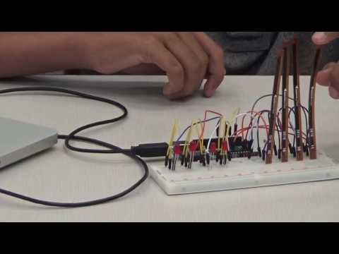
My main difficulty with this project was setting up the circuit, since I do not have much experience with breadboards I had to do a lot of research to figure out how to set up the breadboard to do what I wanted it to do. Due to my lack of experience in breadboards I spent a couple of hours rewiring the entire circuit, to later find out I did not have a wire plugged in and the LED lights were not receiving any electricity. Below is a schematic that I used for my first milestone, using a breadboard was great for this project because I did not have to solder.
Flex photo Flex Sensor Screenshot_zpsavhuyxkv.png

My Starter Project
My starter project is the Big Time Watch. On the watch there is a 32khz Crystal which controls the time, and allows the clock to go from 12 AM to 1AM. This Crystal is used in most watches. The watch came with a pre-programmed ATmega328, which is a microcontroller. The ATmega328 interacts with the Crystal and the Display. The display is a 7 segment display that uses a standard 12 hour clock, and displays the time in blue. On the watch there is a 10 ohm resistor, which is used to reduce current flow, without this resistor the board would short circuit. The watch is using a 20mm Coin Cell Battery, that is being controlled by a Right Angle Tactile Button, and when pushed it will light up the display in blue and tell the time. One of the main challenges I had building this watch was all the soldering, and assembling the laser cut acrylic casing on the watch, I actually ended up breaking one of the pieces of acrylic and had to use tape in order to put it back together. I learned a lot about how to solder, and how currents work. I also learned a lot about microcontrollers from my research.

Comments
  • John Smith
    Reply

    Wow! This is really cool!

Leave a Comment

Start typing and press Enter to search

Bluestamp Engineering