Presentation Night
Reflection
I really enjoyed working on the GLaDOS robot but there were a lot of challenges because I never previously worked with Arduinos or electronics and I have absolutely no experience at all. There were many moments of frustration when parts wouldn’t come together or did not work properly. But besides that, my time here at BlueStamp has been really enjoyable because it’s more of a hands-on program instead of the more traditional paper and pen format. I just loved seeing my project come alive throughout the weeks and I always found myself wanting to come back the next day to continue my work. BlueStamp has not only improved my knowledge in electronics and computer science, but it has also given me the confidence to start projects on my own.
Final Milestone
In the final stages of my project, I finished the wiring, moved all the electronics over to a perf board, and did the movement code that mimicked a scene from Portal.
Wiring and Cord Management
In Portal, you can see that GLaDOS has all these black and yellow wires coming out of the side. This feature came in handy because I needed to supply all the components in the lower half of the robot with power, ground, and data. This means that the wires that you see on my robot are not just aesthetics to mimic the look of the actual GLaDOS but actually serve a purpose. The tricky part is that you have all these black wires that needed to be soldered to a specific place on a specific component. Proper cord management is needed to make sure that every wire is connected to the correct place. I managed to do this by labeling each wire with electrical tape.
Perf Board
Because all the power and data wires are strung through the base in one single bunch, I grouped the wires into 3 sections, power, ground, and data. Each group is soldered to their own pin connectors so that they are able to plug into the perf board. By doing this, I now have the ability to unplug all wires in case I need to remove the perf board for troubleshooting or if I want to add something. The perf board itself contains a capacitor, resistors for the NeoPixels, and connections to the Arduino for data.
Movement Code
Recreating the movements of a scene by manually altering the positions of the servos is a very time consuming and tedious process. To make things easier for myself, I created a section in my code for each second of the scene. Now all I have to do is look at the corresponding timestamp in the scene and alter the positions of the servos to match what I see in the scene.

Milestone #2
In this milestone, I put together the 3D printed parts as well as assemble the majority of the electronics such as the servos and LEDs. The 3D parts have two main sections: the base and the arm. The base was easier to put together but it involved eight pieces that were held together using screws that had to be tightened in a very small space. The arm proved quite a challenge because of all the specific parts and screws that it needed to be put together. There were some screws that were too long such as the ones holding the curved tube to the back piece. These screws had to be cut down so that it would not interfere with the wires that run through that area. The arm also has three micro servos that were a tremendous pain to insert. These servos fit had to be taken apart and put into slots that were significantly sanded down to fit. Speaking of electronics, installing the LEDs were notably easier. The only hard part was soldering all the wires to the eight LEDs especially since they use surface mounting. Each LED needed three wires meaning there were 24 wires that I needed to surface mount. Apart from soldering, all I needed to do was hot glue the LEDs to the corresponding hole in the base.
Milestone #1

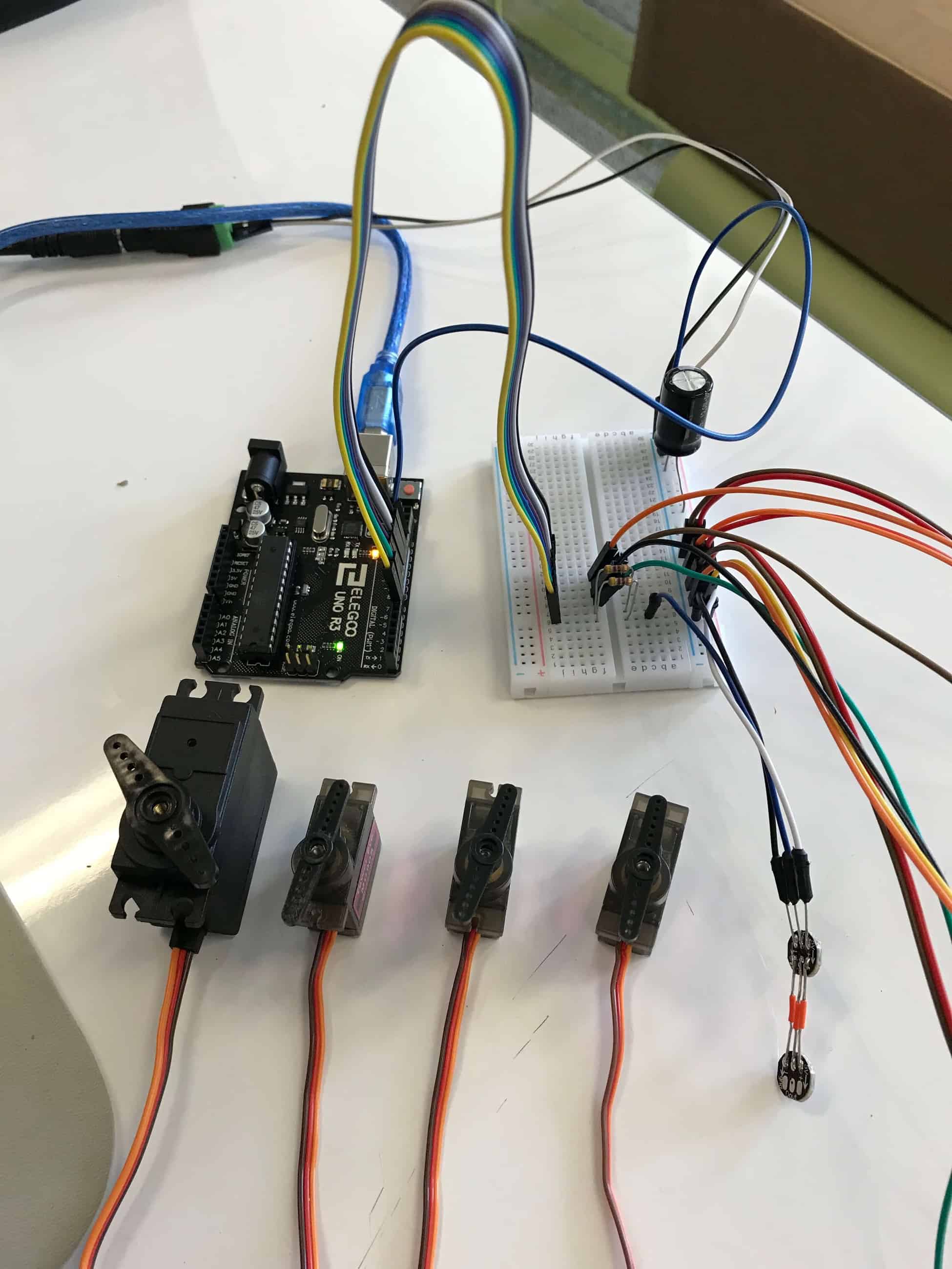
In the beginning stages of my project, I did mainly the breadboarding and the code. For the breadboarding, I connected each of the main components, this includes the four servos and the two LED strands, to an output pin on an Arduino and a five-volt power supply. For the coding portion, this is where I hit a roadblock. I first had to learn how to code in the Arduino language and figure out the libraries that controlled my components. The LED pixels alone delayed me by hours because whatever I did, the LEDs would just not turn. Google search after Google search, I just could not figure out what I was doing wrong. I later found out that I was using a faulty LED and after switching it, the code controlling the LED pixels worked just fine. Even after that, I ran into yet another problem. Learning the servo library went smoothly unlike the LEDs, but I discovered that I had to use a function to control the speed at which the servos rotated. Because of this, new problems arose. The Arduino running this code physically could not perform two things at once. Since the servos needed a function to rotate slowly, this would mean that it would be impossible for them to rotate together. To fix this problem, I found an altered version of the stock servo library that allowed for speed alterations.
GLaDOS Project Resources
All 3D parts used in this project were designed by Yvo de Haas.
Instructions and STL files can be found on his website:
Starter Project


