Smart Home Controller
The smart home controller is able to control various home appliances using different sensors. In this project, I worked with PIR’s, LDR’s, and thermistors in order to control appliances like Christmas lights, lamps, and fans.
Engineer
Sean C
Area of Interest
Electrical Engineering
School
Saratoga High
Grade
Incoming Junior
Reflection
Demo Night and Beyond
Over the past six weeks, I have grown in the fields of mechanical, electrical, and computer engineering. I have faced great struggles and have overcome them. I began the BlueStamp program without any clue about how to complete my project. In fact, my project evolved so much that I didn’t really follow my original build plan and definitely did not use most of my original materials. Even after I had figured out what I wanted to do with my project, I still had a very long road to follow. Much of that road was filled with me researching parts and how to use them, then troubleshooting any bugs. However, these struggles have taught me two great life lessons: how to learn, and how to be adaptable. Overall, my experience with BlueStamp has left me with a greater respect for engineering in general.
Final Milestone
Raspberry Pi Voice Activation
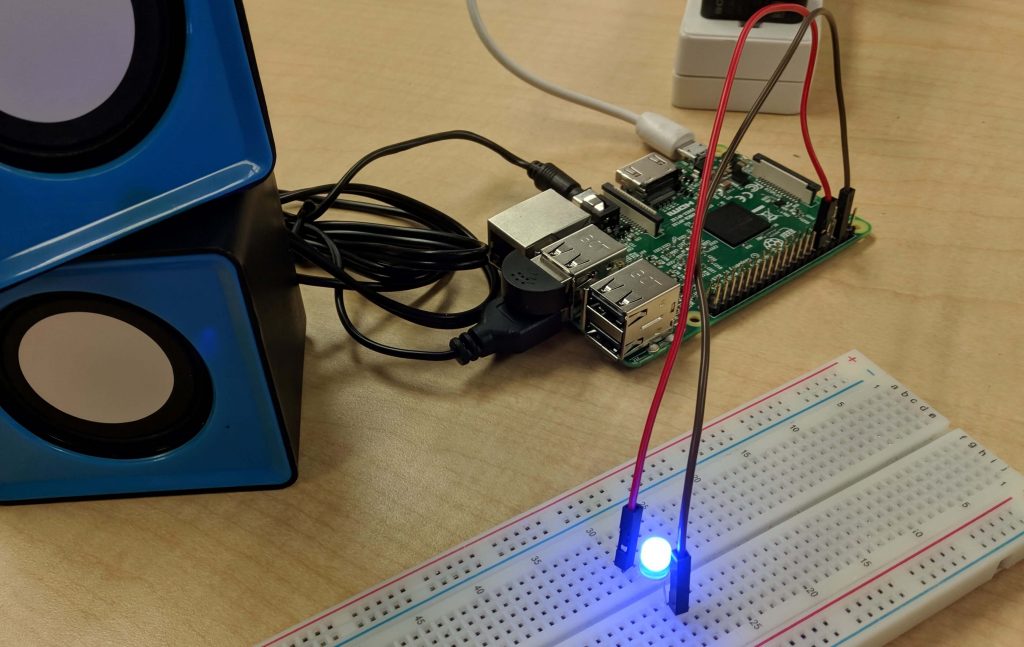
With all the soldering and my main project complete, I moved on to modifications. The modification that I chose was the Raspberry Pi voice activated relay circuit. After saying a few simple words of “Jasper, turn on,” or “Jasper, turn off,” I am able to turn on and off anything that I choose. In the picture to the right I have used a very simple LED circuit, but it would be easy to simply move the wires to the relay in order to get the Raspberry Pi to turn more useful appliances on and off.
The road to getting to the simple voice command stage was quite tough. First, I had to set-up the Raspberry Pi with the operating system Raspbian. Then, I followed a tutorial to install Alexa, got it working, but ran into a road-block when being forced to create new Alexa skills. From there, I moved on to using Jasper, which is an open-source platform for developing voice-controlled applications. I was finally able to write some code to power then turn off my Raspberry Pi’s GPIO pins.

Third Milestone
PCB Relay Circuits

One potential modification that I think would be quite useful for my project would be to add some casings for my PCB’s. After all, even though I have all my wires soldered onto PCB’s I still have exposed wires everywhere. With the casings, I could even add some small placeholders for my wires so it would be easier to wire everything to my Arduino and therefore be easier for me to switch out different sensors for different situations. As usual, I have no idea how to implement said casings but research has not failed in the past and most likely will not fail in the future.
Another modification I could add to my project would be to add voice recognition in the form of Amazon Alexa. Instead of buying an Alexa, perhaps I could make my own with a Raspberry Pi. This modification also seems intriguing but will also require plenty of research. Hopefully, I can figure out something to do and quickly move to improve my project.
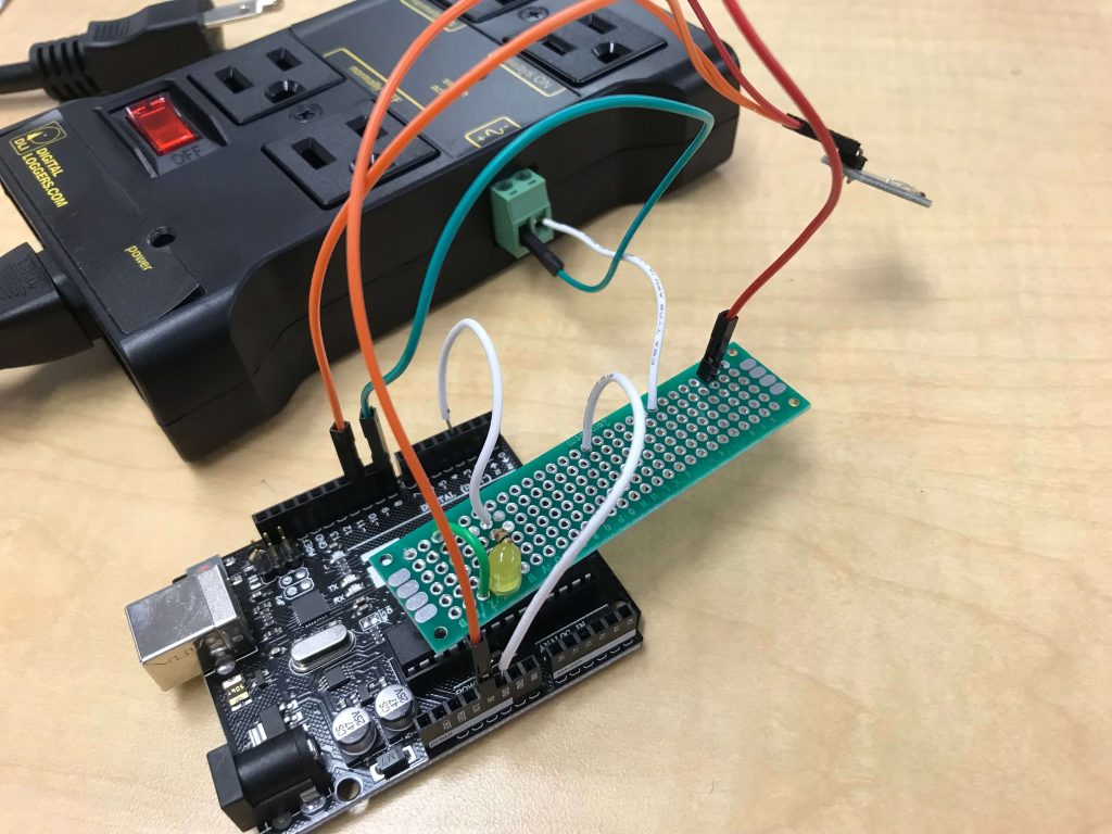
With three breadboard circuits all able to control a relay and the second milestone complete, I began work on my third milestone, which was getting all the circuits moved onto a more permanent fixture. In essence, my entire third milestone was soldering wires together.
Despite the fact that my entire third milestone consists of having myself solder wires, there still was some research to be done. However, this type of research was different, as it mainly consisted of having myself ask various instructors about different soldering techniques. For example, I was confused about implementing a ground rail in my PCB, because, unlike breadboards, the PCB does not connect anything together. Rucha offered the idea that I simply strip a solid-core wire, then attach it to my PCB in order to have a literal metal ground-wire. Using that method, I was able to transfer all three of my breadboard circuits onto PCB’s. Once I verified that everything worked, my third milestone was complete.
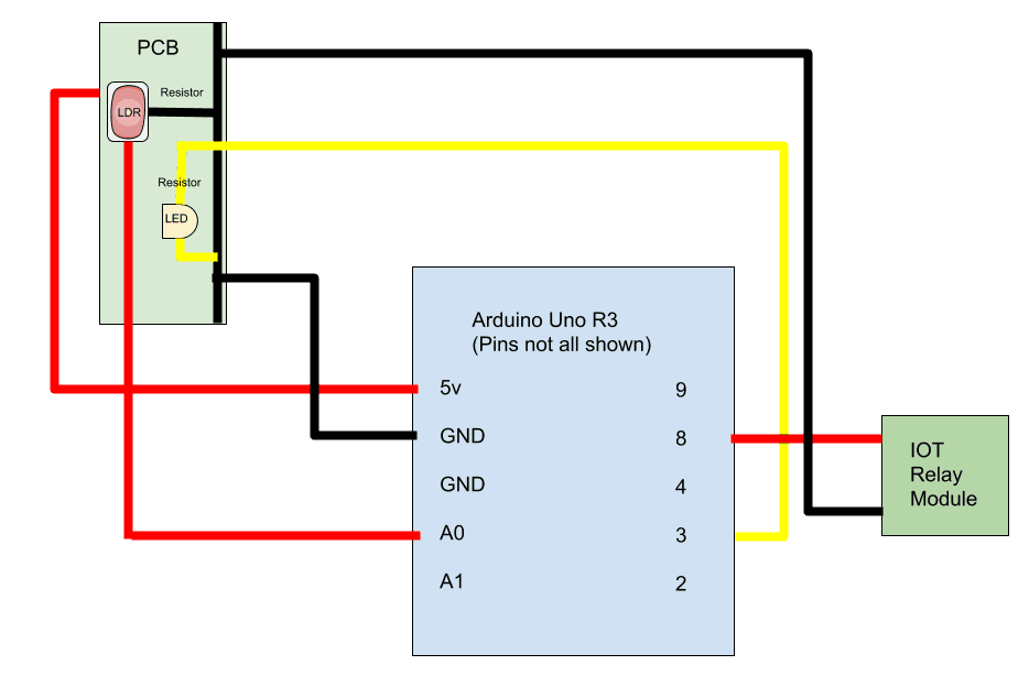
LDR Circuit Schematic
Second Milestone
Research, research, research!
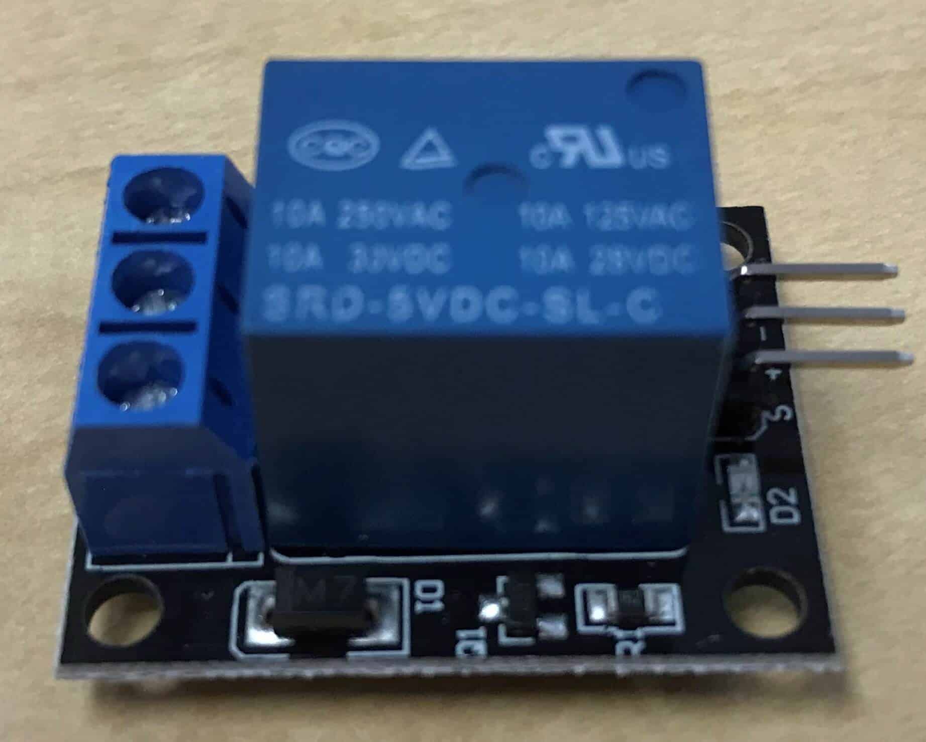
I started the second milestone off with plenty of research. First and foremost was the research of the relay. I found out that a relay is basically an electromagnetic switch that uses input from one circuit to switch on another.
After finishing up the research about the relay modules, I then moved to implement my new-found knowledge into an actual breadboard circuit. I first connected the LDR to the breadboard and hooked it up to an Arduino. Then, after verifying that everything worked, added more wires that connected the Arduino to a relay circuit. The first time I got the relay circuit to switch on would probably rate pretty high on the most satisfying moments of my life.
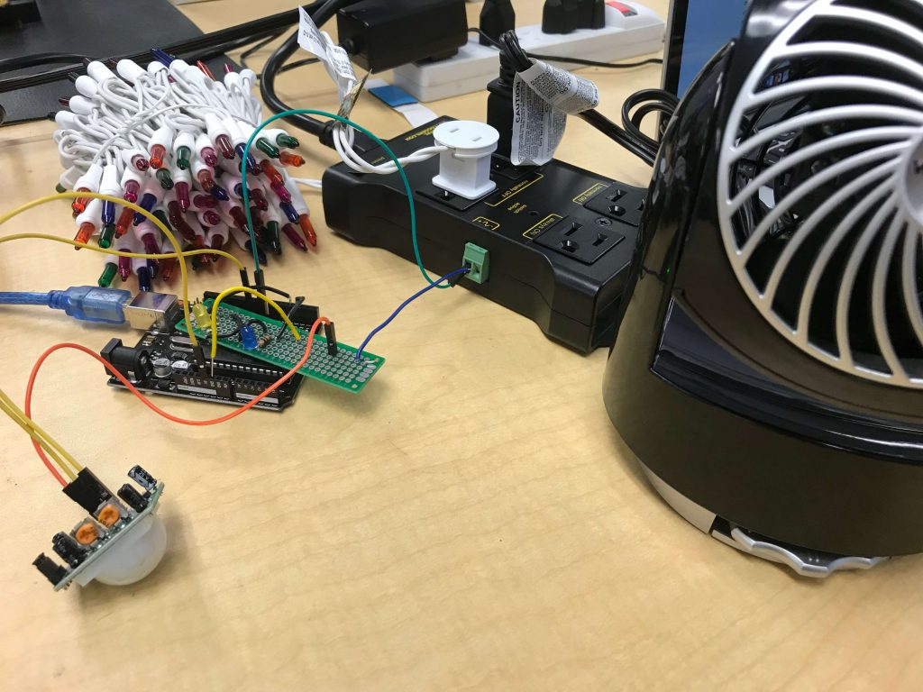
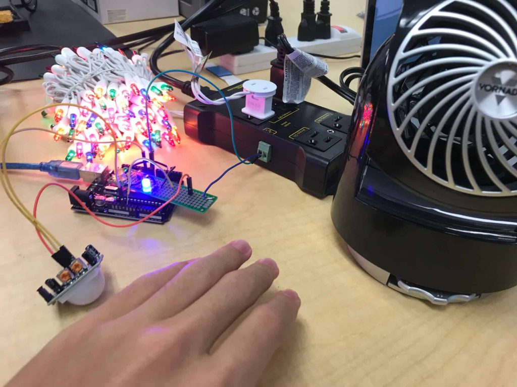
With two relay circuits completed, I decided to add one more to round out my second milestone. This sensor, the PIR motion sensor, was for me the most difficult to work with, simply due to it being complicated. Thankfully, I found a very helpful YouTube video that explained all aspects of the PIR sensor, from the potentiometers that changed sensitivity and time delay to the function of the Fresnel lens located at the top of the sensor. Over the course of a couple of hours, I researched and tinkered with the sensor, finally getting it to turn on a small LED. Then, using my newly-arrived IOT power relay, I got the motion sensor to turn on some Christmas lights and with that completed my second milestone.
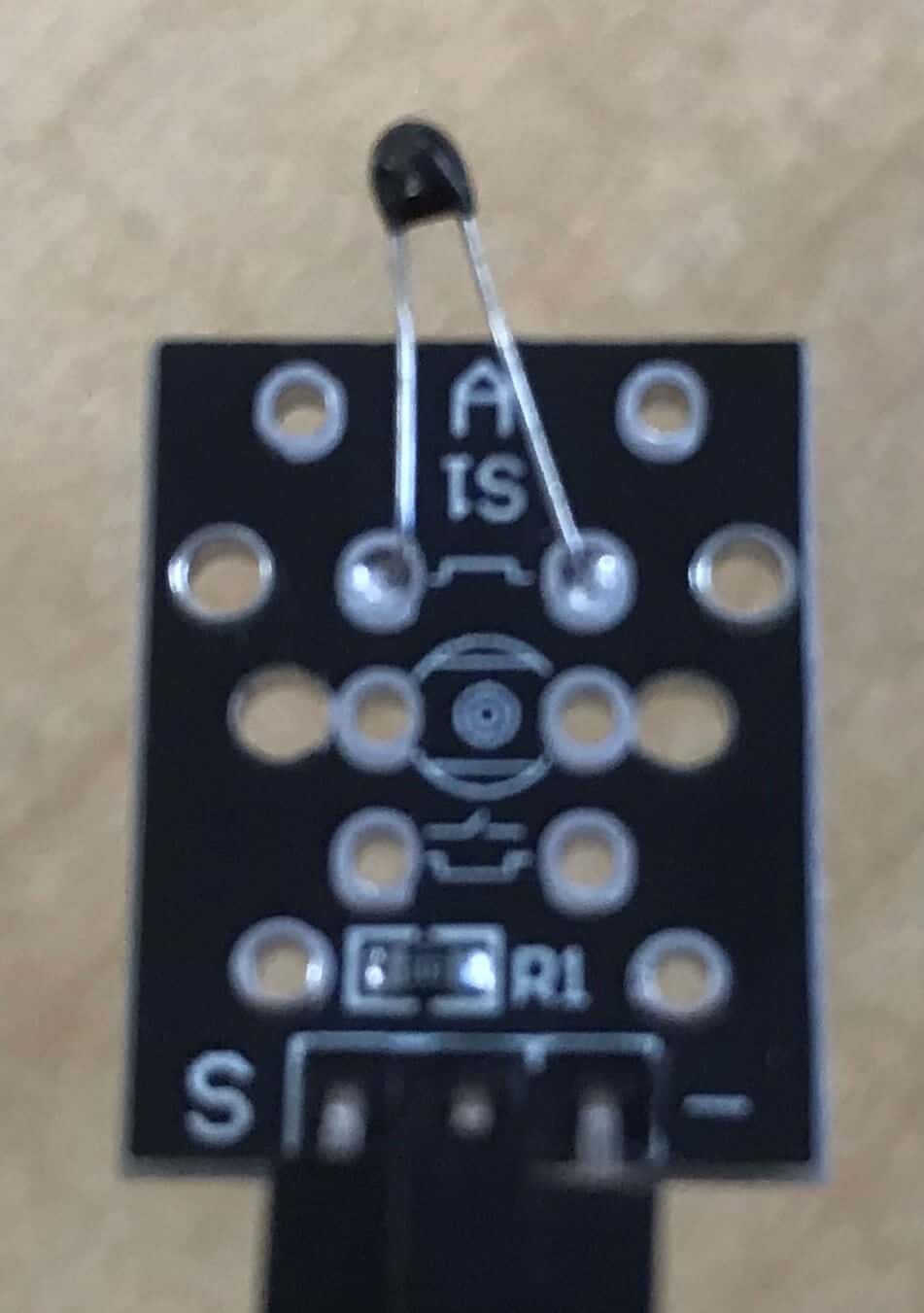
With the LDR-relay circuit working, I decided to add more sensors to my project, not just photoresistors but thermistors and motion sensors too. I first began my research by looking at the thermistor. I learned that the sensor works along the same principle as the photoresistor in that when there are changes in the environment the resistance of the sensor changes.
Once the thermistor research was complete, I began work on creating a relay circuit featuring the thermistor. I just followed the same steps that I took with the LDR to make the circuit, with the Arduino receiving input from the thermistor, then sending output to the relay. One bit that I had trouble with was actually getting the thermistor to actually activate the Arduino output. As with all problems, I researched. Finding that thermistors actually had temperature ratings of a couple hundred degrees Celsius, I touched a soldering iron to the thermistor and quickly saw the Arduino turn on my relay.


// Sean C BlueStamp PA 2018
// setting all the Arduino pins.
int input = 10;
int LED = 13;
int otherLED = 12;
int waitingLED = 7;
int relay = 8;
int value;

void setup(){
  // setting up all the pins
  pinMode(input, INPUT);
  pinMode(LED, OUTPUT);
  pinMode(otherLED, OUTPUT);
  pinMode(waitingLED, OUTPUT);
  pinMode(relay, OUTPUT);
  Serial.begin(9600);
  // delaying to allow the PIR to warm up
  digitalWrite(waitingLED, HIGH);
  delay(60000);
  digitalWrite(waitingLED, LOW);
}

void loop(){
  // getting the input from the sensor
  value = digitalRead(input);
  Serial.println(value);
  // turn on the relay and LED
  if(value == 1){
    digitalWrite(LED, HIGH);
    digitalWrite(otherLED, HIGH);
    digitalWrite(relay, HIGH);
    Serial.println("Motion detected");
  }
  // turn off the relay and LED
  else{
    digitalWrite(otherLED, LOW);
    digitalWrite(LED, LOW);
    digitalWrite(relay, LOW);
    Serial.println("No motion detected");
  }
  delay(1000);
}
// Sean C BlueStamp PA 2018
// defining all the pins
int boardLED = 13;
int breadLED = 10;
int relay = 8;
int thermistor = 3;
int inputValue;

void setup() {
  // defining all the pins
  Serial.begin(9600);
  pinMode(boardLED, OUTPUT);
  pinMode(breadLED, OUTPUT);
  pinMode(relay, OUTPUT);
  pinMode(thermistor, INPUT);
}

void loop() {
  // gathering the input values
  inputValue = digitalRead(thermistor);
  Serial.println(inputValue);
  // turning on LED's and the relay
  if(inputValue == LOW){
    digitalWrite(boardLED, HIGH);
    digitalWrite(breadLED, HIGH);
    digitalWrite(relay, HIGH);
  }
  // turning off the LED's and the relay
  else{
    digitalWrite(boardLED, LOW);
    digitalWrite(breadLED, LOW);
    digitalWrite(relay, LOW);
  }
}
First Milestone
Working Photoresistor Circuits
In my first milestone, I began to understand how both the Arduino and the Breadboard worked. I also began to understand the uses of all of the parts. For example, I researched how a photoresistor works (resistance increases/decreases with fluctuations of light levels). Meanwhile, I also figured out that the orientation of the LED’s actually does matter, a fact that cost me a lot of time to figure out.
I first started with a basic circuit with a single LED. I coded a program to turn on and turn off that LED based on user inputs. There, I found out that if my LED orientation was off, then the circuit wouldn’t work. After making sure that everything worked, I tore the simple circuit apart and began to work on my real “starter” circuit. I followed an online tutorial on how to set up three LEDs with a light dependent resistor. Making sure to be careful about following all the directions, I was able to set up the circuit. After coding the program and uploading it to the Arduino, I saw how the LEDs were switching on and off based on the light level.


The actual program works by first initializing all the values needed. The program sets all the pin numbers as variables. For example, the pin number for the LED representing darkness is 4. When starting, the program defines all the LED pins as outputs. During the loop, the program first places the value of the photoresistor into a variable. Then the program will turn on the light, medium, or dark LED based on the light level. This will continue to happen as long as the Arduino is powered.
One difficulty that I had during the project was just sheer inexperience. I had no clue what the function of many of the parts was. I also didn’t really know how a breadboard worked. Finally, I didn’t have any experience with Arduino at all. All of the inexperience had to be remedied with lots of research, so I researched all about my project for about two days. In the end, though, I was able to achieve a working preliminary project.
// Created by Sean C LDR + 3LED Tester Project 6/18/2018
// initialize the input value integer
int intputValue;

// label the input for the LDR (A0)
int photoResistorPin = A0;

// define the pin numbers for the three LED's
int darkPin = 2; // the LED for dark light levels is located at pin 4
int mediumPin = 3; // the LED for medium light levels is located at pin 3
int brightPin = 4; // the LED for bright light levels is located at pin 2

void setup() {
  // sets up the program before running
  // label all the pins as output pins
  pinMode(darkPin,OUTPUT); // pin 4 is output
  pinMode(mediumPin,OUTPUT); // pin 3 is output
  pinMode(brightPin, OUTPUT); // pin 2 is output
}

void loop(){
  // Arduino loops through this code when running
  intputValue = analogRead(photoResistorPin); // sets inputValue as the photoresistor level.
  if(intputValue < 40){
    // if the input level (photoResistor level) is less than 50, the LED representing darkness will turn on
    digitalWrite(darkPin, HIGH);
  }
  else if(intputValue >= 40 && intputValue <= 80){
    // if the input level is between 50 and 80, then the LED representing medium light levels will turn on
    digitalWrite(mediumPin, HIGH);
  }
  else{
    // if the input level doesn't match the previous paremeters (if it's too high) then the LED representing brightness will turn on
    digitalWrite(brightPin, HIGH);
  }

  delay(200); // delays the program 200 milliseconds

  // turns off all the pins
  digitalWrite(brightPin, LOW);
  digitalWrite(mediumPin, LOW);
  digitalWrite(darkPin, LOW);
}
Starter Project
Useless Machine
