RC Hovercraft
I am building the RC Hovercraft, a vehicle made out of depron, capable of hovering and navigating on several different kinds of surfaces. My hovercraft uses 2 motors, one for lift and one for propulsion, as well as utilizing 2 batteries to power the motors work, with a nylon skirt at the bottom.
Engineer
Sami M
Area of Interest
Electrical Engineering
School
University High School
Grade
Incoming Junior
RC Hovercraft Showcase Video
BlueStamp Reflection:
During my time at BlueStamp Engineering, I learned so many things about different kinds of engineering that I didn’t realize were important or relevant. My lense was widened to engineering as a whole and what goes into being an engineer. The program itself did a good job of challenging us students and forcing us to problem solve and work out our own problems. I believe that the program model BlueStamp has of being a place to “just build” is ideal for someone trying to learn about engineering. My project, the RC hovercraft, was a really fascinating and enjoyable project and taught me more about the physics of aeronautical engineering and the mechanical designs of building a proper hovercraft. There were some really rough patches with the skirt sewing that took an extremely long time, balancing the hovercraft, and trying to get all of the wires and electronics to fit inside the hovercraft. However, in the end, the product is awesome and definitely worth it for the hard work that went into building it.
Although I really enjoyed my project and thought it taught me a lot about mechanical engineering, after looking back on my opportunities here, I wish I did a project that involved more electronics and software engineering, because the hovercraft didn’t require much electronical development, while a lot of the other projects had a lot more electronic development and software writing. Such skills are something I feel would’ve been really beneficial for me if I were to learn more by doing a project like that. Nonetheless, BlueStamp has inspired me to build more projects on my own as well as try to expand on my engineering skills in school, college and future internships.
Modification #1: Utilizing an Arduino & LEDs
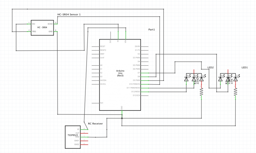
My 4th milestone, my modification milestone, included me adding several LED lights onto the front of my RC hovercraft and controlling the colors of the neopixels using an Arduino and ultrasonic sensor. First, I had RC LEDs that were connected straight to the receiver and turned on when the batteries were plugged in. That step was very straightforward and didn’t take much work to do. However, my next step was trying to get my ultrasonic sensor to communicate with my neopixel lights. My main goal was to get my hovercraft to almost emulate the aesthetics of a police car, and to do that I needed some police lights. What I wanted to do was have it so whenever the ultrasonic sensor detected an object in front of it within a certain distance (90-100 cm), then the neopixel lights would start flashing red and blue, and when the object got closer, the lights would start flashing red and blue more quickly. In order to do this, I coded out multiple commands that told the neopixel lights that whenever there was something detected, lights would turn on and off and alternate. There were multiple challenges with coding this out and for most of this code I had to come up with the commands myself because I couldn’t find any clear direction online. Finally, after constant trial and error, plugging in things to my Arduino, and breadboarding, I was able to get it to work properly and have police lights on my hovercraft. After I shot my video, I had some extra time, so I decided to add a paint job to make my hovercraft look nicer and more aesthetically pleasing without being too colorful or distracting.
To get the base code to connect LEDs to the sensor before making my own code I used this source: Link
Arduino Modification Schematic
Final Milestone: Inserting the Electronics & Base Project Done
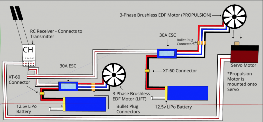
My final milestone covered all of the electrical development, testing, and arrangement within my RC hovercraft, and putting it together to complete my base project. I was using RC electrical parts, which doesn’t require a breadboard to test or work with. Those electrical parts included two Brushless 3-phase EDF Motors, one for lift and one for propulsion, two Electronic Speed Controllers (ESC) , two 12.5 Volt LiPo batteries, a servo, a receiver and a transmitter. The motors interact with the ESCs in a very interesting way, where each motor has 3 different power phases, seen by three different wires coming out of the motor. Depending on how the wires are connected to the ESCs, the power will create a magnetic field that will rotate the motor, which will push the air in a certain direction, pushing the motor and hovercraft in the other direction. If the lead connections between the ESC and motor are changed, it will change the rotation of the motor, in turn changing the direction of the motor’s force applied. ESC and the Motor’s wires are connected by bullet plug connectors, small metal rods and holes that connect together to make electrical connections. The ESCs are essential for allowing the user with the transmitter to properly control and manipulate the speed and power of the motors. Without an Electronic Speed Controller, you wouldn’t be able to control the speed of the motor, and it would just go at the speed of whatever current was being sent to the motor. With the ESC, you can control the current that’s being passed through the wires to the motor, therefore controlling the power output and speed of the rotations of the fan motor. The ESCs are able to communicate with the transmitter via the receiver. Depending on which channel the ESCs are plugged into on the receiver, the ESC will respond to a certain command, button, or joystick on the transmitter to make it work.
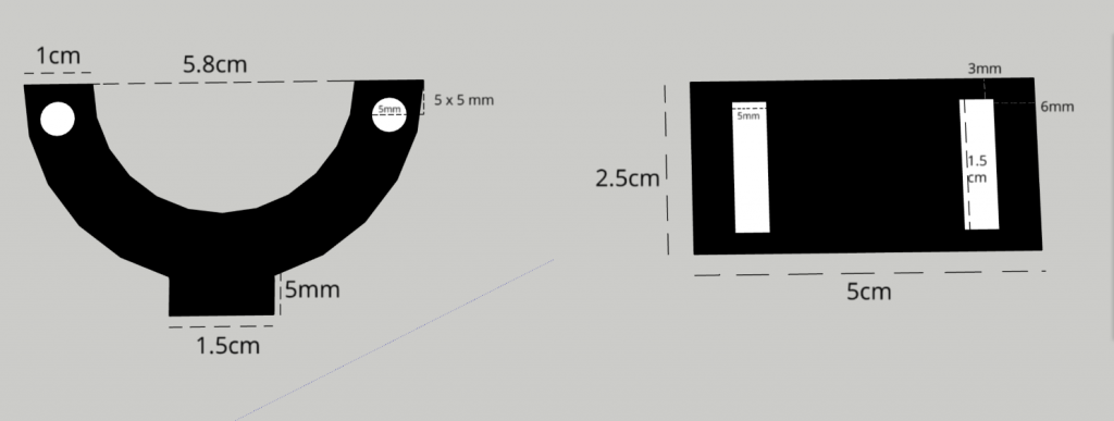
Another challenge I faced when connecting the electronics and getting them to fit properly in my hovercraft was with the mounting of my propulsion motor onto my servo. Having a strong and secure mounting of my propulsion motor to my servo was key to making sure that my hovercraft was durable and wouldn’t fall apart. What I ended up doing is making a properly dimensioned drawing of two half-circles with two holes going through each of them, as well as a plastic platform with two rectangular holes. The dimensioned drawing was then mapped out on the CNC machine and cut out. After the shapes were cut out, the half-circle shapes were then hot-glued to the propulsion motor, fitting perfectly into the cylindrical shape. I then looped zip ties through the holes drilled into the half-circles and going around the motor to give an extra layer of security. Each of the half-circles has a small lip at the bottom, which fits perfectly into the holes cut out on the plastic platform that was also cut out. That plastic platform was then screwed onto a plastic servo stand, which then screws onto the servo.
After I inserted all of the electronics, I was finally able to test drive my hovercraft. However, it didn’t go as planned. The hovercraft didn’t hover properly, and it was extremely unbalanced. I had two main problems; weight distribution and skirt design issues. First, the inside compartment of my hovercraft was too skinny to evenly distribute the weight across both the x and y axis of the base. Therefore, I decided to cut holes on the sides of my compartments, and slip my batteries through there, so they were in the little spaces on either side that are between the slanted wall on the outside of my hovercraft and the inside wall of my compartment. By doing this, I was able to properly distribute the weight more evenly and in turn create a more balanced hovercraft. After my weight problems were fixed, there were still problems with my skirt. The design of the skirt had my bottom open pieces held together by strips of nylon, that made sure the skirt stayed firm and didn’t blow out to the side when I turned my lift motor on. However, the problem was that if there was any slight imbalance in the lift motor, air flow, or weight distribution, the entire hovercraft would hover lopsided due to one side of the skirt pulling the other side of the skirt via the nylon strip holding them together. To fix this, I taped down certain parts of the skirt in order to balance out the max volume the skirt can have at certain places to make it evenly hover and properly move. It still has a slight imbalance, but it’s not enough to affect the hovercraft when it’s moving at a decently fast speed. Overall, even though there were times of struggle and frustration, I really enjoyed the process and thought that all of the complications and problems were worth it to have an amazing project.
NOTE: The main instruction I received came from this instructable for making my hovercraft, however lack of clarity in the documentation led to myself and others building the hovercraft to not follow all of the steps completely. Link
Electronics Schematic + Servo Mount Dimensions
Bill of Materials
| Item | Vendor | Part Num | Quantity | Price | Link |
| 6mm Gray Depron | RC Foam | 10-905 | 1 (10 pack) | $10.00 | Link |
| 55mm 3-Phase EDF Motor | Amazon | N/A | 2 | $27.99 x 2 | Link |
| Servo Motor | Sparkfun | 11965 | 1 | $12.95 | Link |
| GooLRC 2A 2.4GHz Radio Transmitter w/Recevier | Amazon | N/A | 1 | $54.99 | Link |
| 12.5v 1300mAh LiPo Battery | HobbyKing | 9067000328-0 | 2 | $7.24 x 2 | Link |
| 30A ESC | HobbyKing | 9164000035-0 | 2 | $12.46 x 2 | Link |
| P606 Lipo AC/DC Battery Charger | Amazon | N/A | 1 | $37.66 | Link |
| RipStop Nylon Fabric | Amazon | N/A | 1 | $8.95 | Link |
| XT-60 Connectors | Amazon | N/A | 1 (10 Pack) | $8.68 | Link |
| Bullet Plug Connectors (3.5mm) | Amazon | N/A | 1 (10 Pack) | $7.99 | Link |
| Uno Arduino (MODIFICATION) | Mouser Electronics | 782-A000066 | 1 | $22.00 | Link |
| H-SRO4 Ultrasonic Sensors (MODIFICATION) | Amazon | N/A | 1 (2 Pack) | $8.99 | Link |
Hovercraft Build Plan
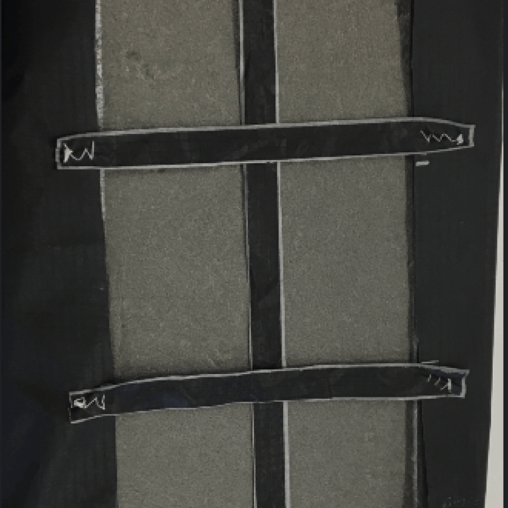
Second Milestone: Making the Skirt
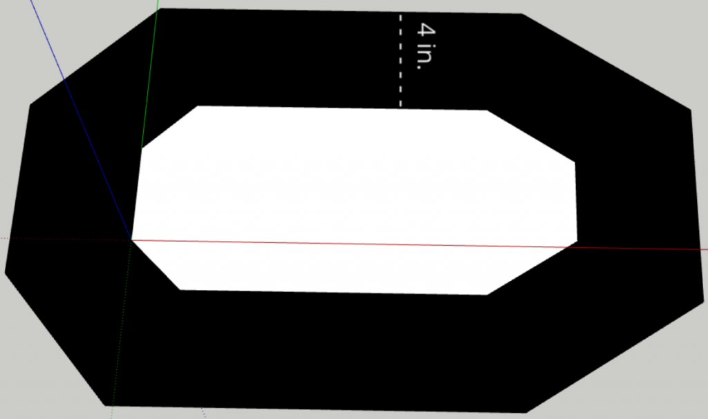
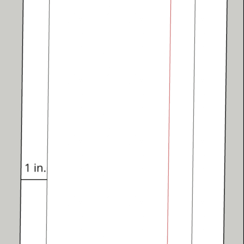
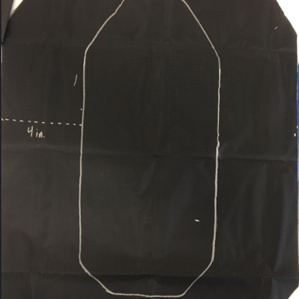
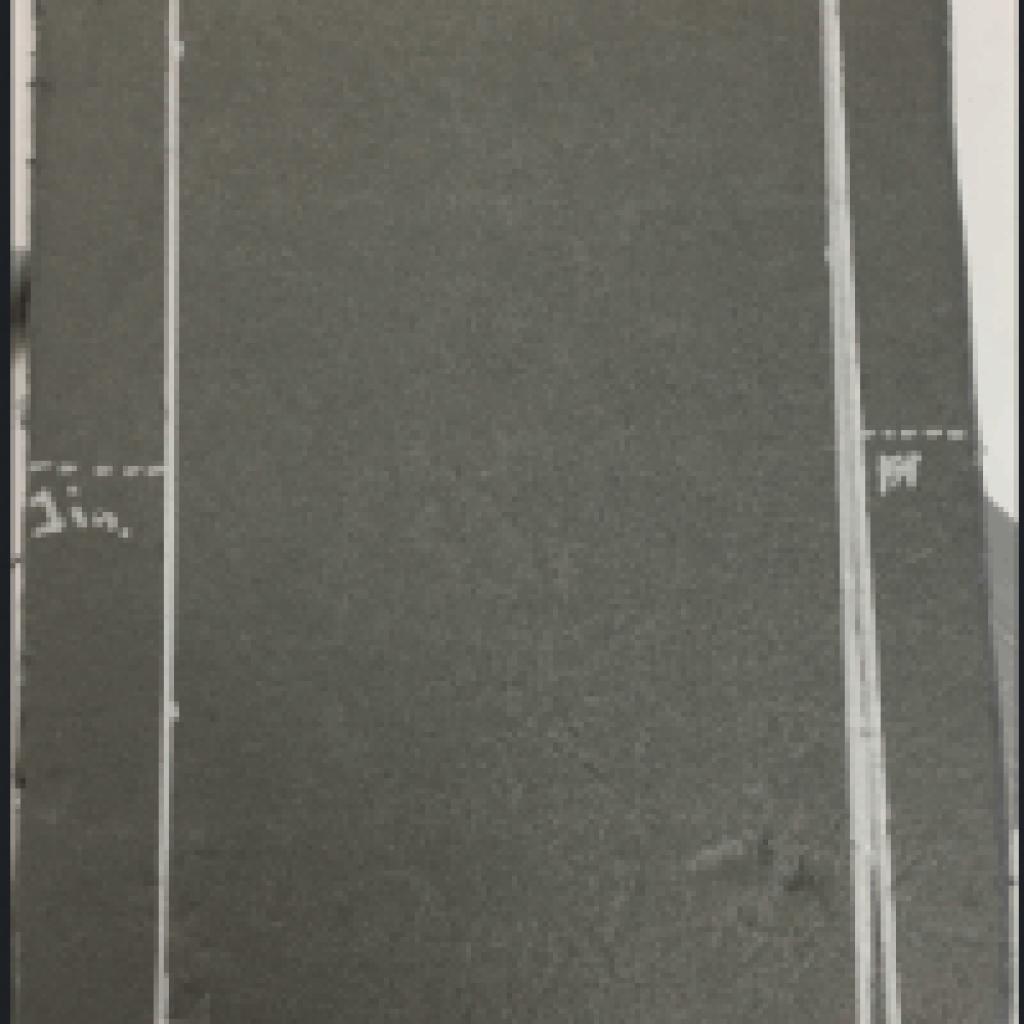
For my second milestone I completed the skirt for my hovercraft, the final mechanical component needed for my project before I started working on the electronics. The material used for the skirt was made out of a certain black nylon ripstop fabric that worked perfectly with shaping the proper skirt for my hovercraft. In order to cut out the proper shape for my skirt, I set my body over a large flat piece of nylon fabric, and measured 4 inches out from my body on every side and angle, to make a larger body outline marked on the skirt to cut. After I cut out the nylon from the outline I made, I then cut out all the fabric that was underneath the body when I put it on top of the fabric. After I had the 4 inch wide cut out piece of fabric shape like my body, I started to measure out my distances for folding the fabric onto the body in order to leave enough space for air to flow throughout the skirt. On the top portion of the body, I folded the skirt in 1.5 inches, and on the bottom part, I folded the skirt in 1 inch. After manipulating and folding the skirt to make the right shape to fit onto my body, I started the grueling process of attempting to sew together each of the folds of fabric at the corners of my body. At first, the sewing was extremely difficult due to the fact that I hadn’t sewn before in my life, but after a few tries of getting it right and eventually starting over, I started to get the hang of it. In order to get the right fold amount and sew it tightly, I taped down both sides of the skirt to the body before sewing, and then for every fold I needed to sew, I would remove only that portion of tape while leaving the rest of the tape on to get the perfect shape for my skirt. After 3 days of sewing, I finally completed my skirt. I used super glue and duct tape to attach the top side of the skirt to the body while leaving the bottom side open yet held together with strips of fabric, so it doesn’t blow out while hovering.
Many people may be asking, “What’s the purpose of the skirt? What does it do to make the hovercraft actually hover?”, and to that comes a lot of physics about air flow and circulation. Before the skirt is filled with air, the bottom of the skirt creates a seal with the ground due to gravity. Once the motor is turned on and air starts to flow into the skirt, it starts to fill up like a balloon, quickly increasing the pressure inside the skirt. That pressure built up inside the skirt wants to escape, and the only way out is to break the seal between the ground and the bottom portion of the skirt. Once enough air pressure is built up and the seal is broken, the air coming out of the skirt and out of the hovercraft starts to flow at the same rate of air being blown into the skirt itself, therefore leading to the hovercraft hover perpetually.
Skirt Designs + Cut Outs
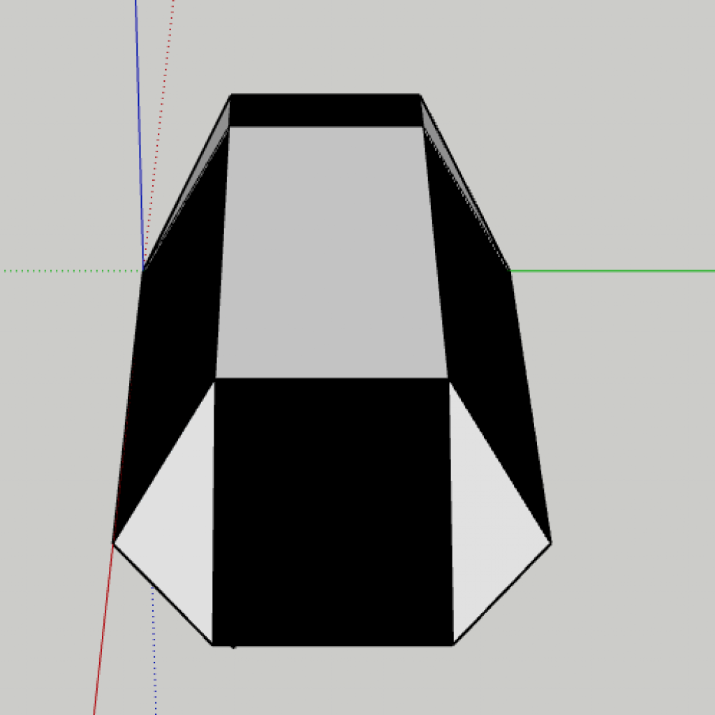
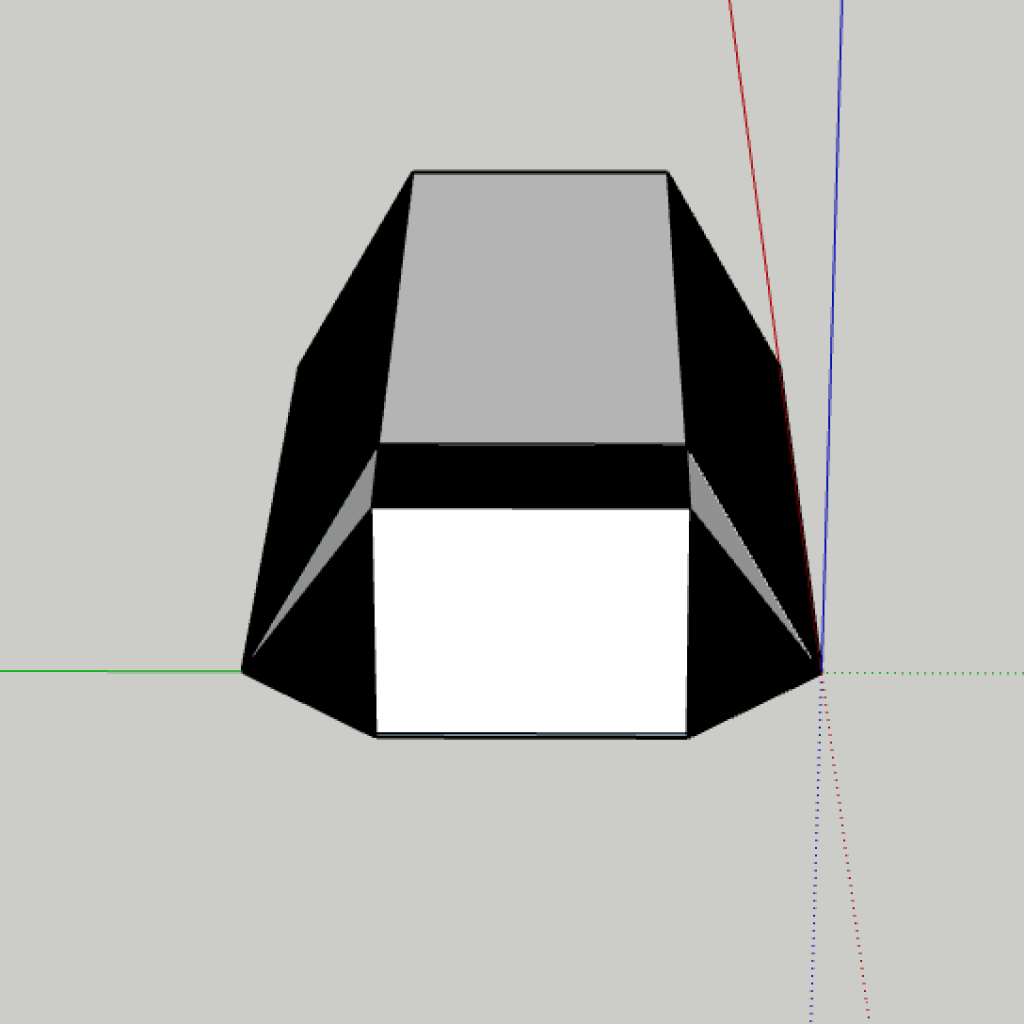
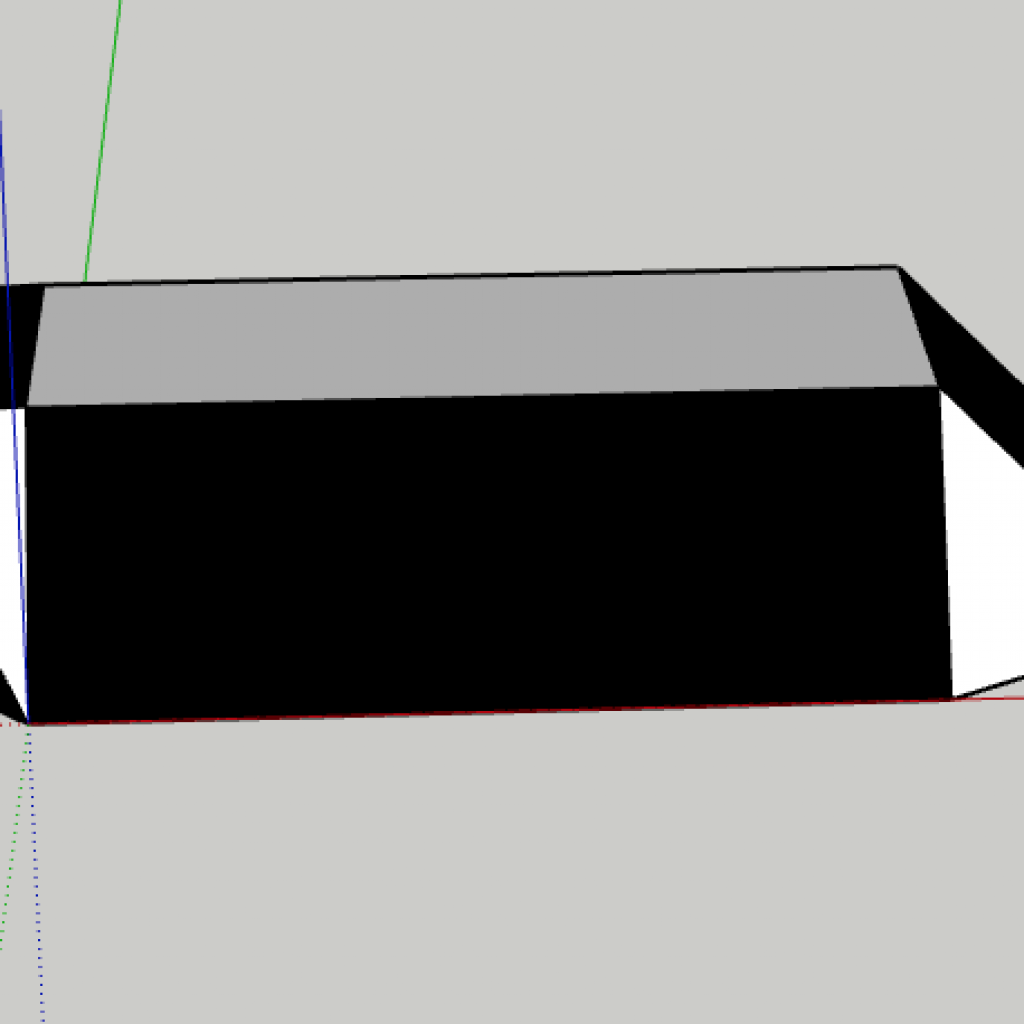
First Milestone: Building the Body
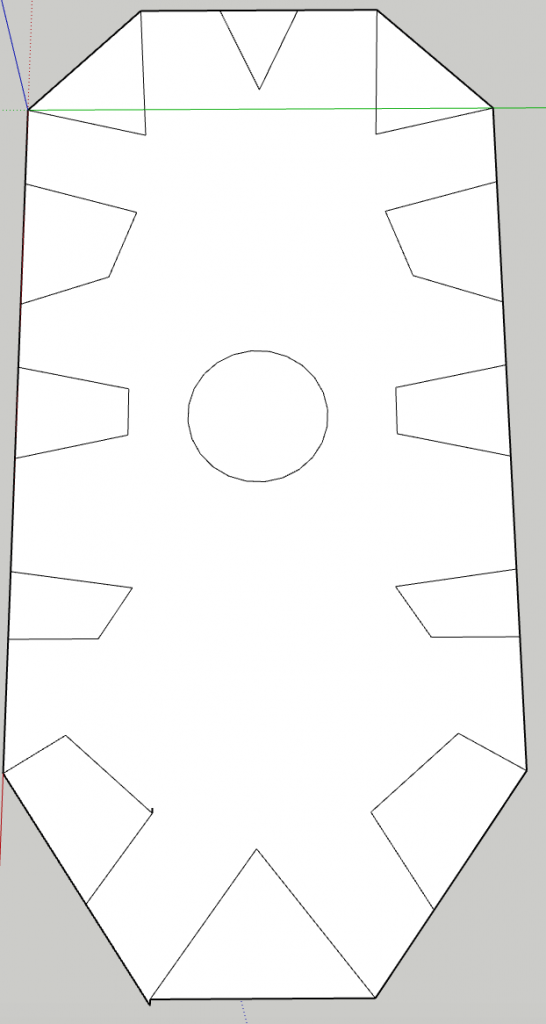
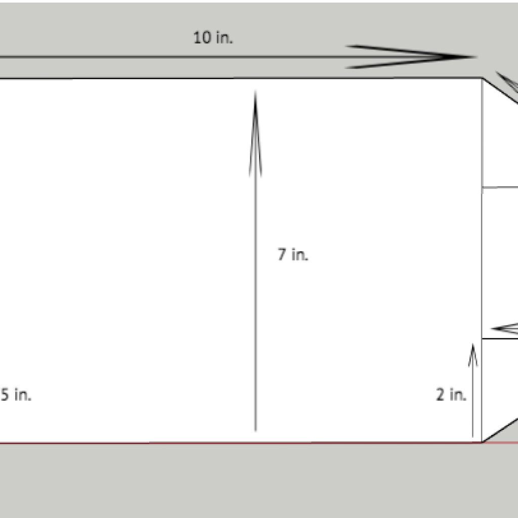
Throughout the first few days of starting my intensive project, the RC hovercraft, I have primarily spent my time cutting out depron and putting together my body for the hovercraft. Depron is the main material used to make the body of the hovercraft, and it’s basically an extremely light foam that can hold its shape without being bent too hard. The base shape of the hovercraft consists of an 8-sided shape that is roughly 14.75 inches long and 7 inches wide. The base has 4 layers in total that are hot-glued together, however I haven’t connected the top layer to the bottom 3 because I still need to make the skirt that will go in between the two layers. The first layer is just a plain cut out of my base shape with no internal holes or cuts, the second layer is a much weirder layer, having a ton of cut outs within the main shape in order to create air holes for the fan to blow out into the skirt. The third layer goes on top of the cut out second layer, and it’s a normal shape of the base, except it has a hole cut out for the hover motor to blow air through. Finally, the fourth layer goes on the top of the base of the hovercraft, and it’s the same design as the third layer of the base. As far as the 3D body and walls of the hovercraft, I made it quite simple, just having a rectangular box in the middle 10 x 3.5 inches and slanted walls on either side. The front has a square and two triangles that fit into to give the hovercraft the somewhat aerodynamic shape, although the overall shape of my hovercraft is quite boxy. The back section of the hovercraft I haven’t built yet because I still need to put in the servo and motor to determine how I’m going to construct the back to fit in those electrical components.
An issue I ran into while building my skeleton was the hole placement on my base. At first, I had the hole placement way too far back, around 2 inches from the very end of the hovercraft. Since the hole was that far back, it was hard to get the center of gravity correct in order to have the hovercraft be balanced. When I realized that the hole I had was too far back, I then cut open the base layers that were already hot-glued together, cutting a new hole in the middle of the base, and filling the old hole with depron and spackle.
Hovercraft Body Diagrams
Starter Project Milestone
The Starter Project I built was the LED Motion Controlled Light Show, a device that emits certain colors of LED light that is determined by your hand placement over the 3 IR sensors on the PCB. On the PCB, there are several electrical devices and components that make this device function. There are two 0.1uf capacitors and one 220uf capacitor, which in a circuit are used to store electrical power and act as temporary batteries. There is an IC Socket that is meant to hold the integrated circuit, which has a mini circuit inside of the IC. The IC unit holds the microprocessor inside of it that reads the movement detected from the sensors and transfers that data into emitting certain LED colors on the strip. The Terminal Block and Barrel Jack are used both for connecting the PCB to other devices, the 5v barrel jack connects the PCB to the power source, a 5v AC Adapter, while the terminal block connects the PCB to the 16 LED strip. Furthermore, the way that the device detects motion is through utilizing 3 TCRT IR sensors. The IR sensors consist of two different parts, an Infrared LED that emits invisible infrared radiation in a beam, and a phototransistor which is a type of transistor. Traditionally, a regular transistor works by allowing the flow of current to pass from the emitter to collector by putting in current from the base into the transistor, changing the voltage of the circuit on the other side. The phototransistor allows the flow of electrons to pass through the circuit (emitter→ collector) only when it is exposed to infrared light. In order to get the phototransistor to absorb that infrared light, you need to put your hand over the sensor, which reflects that infrared light coming from the IR LED into the phototransistor. The microprocessor in the circuit then reads how much voltage is produced by each phototransistor in their respective sensor, and then tells the LEDs to emit light on the strip according to how much voltage is produced by a specific sensor. The 3 sensors create 3 different colors; green, red, and blue, and those colors can be combined and different colors can be made when there are voltages produced from more than one phototransistor, meaning your hand is over more than one sensor.
Since there were no schematics provided for the circuit board of my project, it was hard to explain in detail relevance of all of the electrical components and how they affect the project as a whole. However, there is an explanation for the presence of the multiple resistors within the PCB. Generally, LEDs turn on and consume about 3V, and if the voltage is slightly increased the LEDs will consume a ton more current, and if the LEDs consume a ton more current than it’s supposed to, it will burn and fry up. Since the power source going into the barrel jack is 5 volts, that means that resistors are necessary to bringing the voltage of the circuit down to 3 volts, allowing the LEDs to light up without getting burned