
Hello! My name is Sakura, and I am a rising junior at the Brearley School in NYC. As a coder and computer science enthusiast, I have always been passionate about creative problem-solving, algorithmic thinking, and the innovative realms of technology and engineering. Prior to Bluestamp, however, I had mostly only engineered software, and did not have any hands-on experience with hardware (electrical and mechanical engineering). I saw Bluestamp as an incredible opportunity to explore unfamiliar engineering fields, advance my technical abilities, and gain knowledge that allows me to think about novel solutions to real-world problems that integrate different types of engineering. My self-proposed, self-defined intensive project during the six week program encompasses these ambitions. I hope to bring the insight I acquired at Bluestamp to future projects as I pursue my interest in engineering, coding, and robotics.
Update as of June 2016:
My final project is featured as a winner of the CE Week’s “10 Under 20: Young Innovators To Watch” Award! Huge thank you to my mentors and peers at Bluestamp for their support throughout my project’s development!
Prosthetic Hand Controlled by Glove Gestures

Final Milestone: Hand Assembly and Servo Control of Fingers
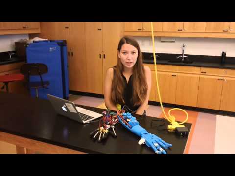
My 3rd milestone consisted of assembling the parts of my 3d printed hand, attaching pulleys to my servos, and inserting threads through the hand which bend and flex the fingers according the rotation of the servos.
To begin, I developed a plan for the pulley system that would control my fingers. I determined that an inner string, when pulled, would bend the finger, and an outer string would flex the finger. With the servo at the position 0 and my finger flexed, I made sure that the outer string was wrapped around the pulley and the inner string was ready to be pulled into the pulley when the servo changed to 180. I also had to change my program to adjust the direction in which my pulleys rotated.
Now, when the flex sensor is bent, the code signals the servo to rotate counterclockwise, thus pulling the inner string and bending the finger; Likewise, when the sensor is flexed, the code signals the servo to rotate clockwise, thus pulling the outer string back into the pulley and flexing the finger.
Securing the thread through the fingers to implement this pulley system was an extremely tedious process, because some of the fingers’ joints had friction and would not bend without a forceful pull on the string, and pulling on the string too strongly caused knots to come apart sometimes. To troubleshoot, I filed the plastic of the tighter joints to allow for frictionless bend and flex movements. eventually, I was able to twist the pulley back and forth to control the fingers.
Finally, I programmed the servos to the most counterclockwise position and attached the pulleys to the servos while the bend string was pulled tightly, to make sure the servos were capable of pulling enough string to bend the finger.
 |
 
|


Bill of Materials
| Description | Vendor | Qty | Cost | Link to Where to Purchase |
| MG946R Servos (or equivalent – MG995 or MG996 should work too). | ebay | 5 | 30.00 | http://www.ebay.com/itm/1-x-MG946R-Digital-Micro-Metal-Gear-55g-Model-Tower-Pro-Servo-For-RC-Car-/111720153793?pt=LH_DefaultDomain_2&hash=item1a030a42c1 |
| 4.5 inch flex sensors | Adafruit | 5 | 64.75 | https://www.adafruit.com/products/182 |
| Arduino Unos | Arduino | 2 | 24.95 | https://www.arduino.cc/en/Main/arduinoBoardUno |
| Xbee | Sparkfun | 2 | 51.9 | https://www.sparkfun.com/products/11217 |
| Xbee shield | Sparkfun | 2 | 29.9 | https://www.sparkfun.com/products/12847 |
| 22k resistors | ebay | 5 | 4.49 | http://www.amazon.com/22k-Ohm-Resistors-Watt-Pieces/dp/B00B5RMYBK |
| 9V Power supply | Amazon | 1 | 9.49 | http://www.amazon.com/Planet-Waves-9V-Power-Adapter/dp/B00191WVF6 |
| Right hand glove (should be sturdy and fit well) | Amazon | 1 | 8.83 | http://www.amazon.com/Ironclad-WCG-05-XL-Workcrew-Gloves-Extra/dp/B000BZ4T10/ |
| Small blank PCB | Adafruit | 2 | 0.95 | https://www.adafruit.com/products/589 |
| Male-male jumper wires | Amazon | ~20 | 5.29 | http://www.amazon.com/Breadboard-Jumper-Wire-75pcs-pack/dp/B0040DEI9M |
| Female-male jumper wires | Amazon | ~20 | 4.01 | http://www.amazon.com/Jumper-Wires-Premium-200mm-Female/dp/B008MRZSH8 |
| Male-male header pins | Sparkfun | 13 | 1.50 | https://www.sparkfun.com/products/116 |
| Female-male header pins | Sparkfun | 64 (order 2 packs) | 3.00 | https://www.sparkfun.com/products/115 |
| 8mm x 60mm bolts | Bolt Depot | 2 | 1.00 | https://www.boltdepot.com/Product-Details.aspx?product=6305 |
| 3mm x20mm screws | Bolt Depot | 10 | 1.00 | https://www.boltdepot.com/Product-Details.aspx?product=6869 |
| M2-0.4 Thread Size, 12 mm Screws | Bolt Depot | 6 | 0.30 | https://www.boltdepot.com/Product-Details.aspx?product=17962 |
| 5m of fishing line string | Amazon | 1 | 12.99 | http://www.amazon.com/Stren-Superline-Lo-Vis-150-Yard-50-Pound/dp/B00LDYNN1U/ |
| Sandpaper or filing tool | Amazon | 1 | 2.01 | http://www.amazon.com/gp/product/B00Y1YM7C0/ |
I also used a Makerbot Replicator 2X 3D printer, power drill, hot glue, super glue, needle and thread.
Code
Milestone #2: Programming the servos to rotate by an amount proportional to the bend of the flex sensors.
My second milestone consisted of programming the servos (that will help bend and flex the fingers of my hand) to rotate proportionally to the bend of the flex sensors. The servos require a power supply to run, so I used a multimeter to determine the positive and negative wires of a 5V power supply, and soldered the wires to their respective charges’ rails of a printed circuit board (PCB). Then, I soldered the servos’ positive (red) and negative (black) wires to their respective charges’ rails on the same PCB, so that the voltage running through the rails can power my servos.
In order to control the servos using my Arduino, I plugged the servos’ signal wires into the Arduino’s digital pins. Then, I wrote a program which measures flex sensors’ levels as analog input and controls servo pins as digital output. The Arduino computes any given flex sensor’s value as a 10-bit representation of the circuit’s divided voltage, and displays a number roughly between 400-700 to indicate its bend. My challenge was writing code which converts that 400-700 number to a proportional value between 0-180 which can be signaled to the servo, so that the servo rotates by an amount corresponding to the bend of the flex sensors. I called this new, corresponding position a variable called P, and using proportions, calculated that:
Range of possible flexValues = 700 – 400 = 300
currentFlexVal/300 (range 0f flexValues) = P / 180 (range of position)
300*P=180*currentFlexVal
P=0.6*currentFlexVal
Knowing that the new position=0.6*currentFlexVal, I created my own mapping function called findPosition which takes in the current flex value and returns a proportional position between 0-180 to send to the servos. My complete program can be accessed here: runServo code.

Figure 4: Schematic of all components and connections, including flex sensor circuit, Arduino, and servos.
Milestone #1: Creating a circuit for the flex sensors and establishing communication between the flex sensors and the Arduino.
Inspiration:
In defining my project, I was certain that I wanted to build something has application potential in the real world. As innovative prosthetic limb technologies are on the rise and more advanced capabilities are being explored every day, I became very interested in building my own 3D printed prosthetic hand that mimics biological, human movement. Furthermore, rather than making a robotic hand that simply does what it’s pre-programmed to do, I would attach sensors on a glove which interpret one’s human bending movements as they happen and would write code that automatically signals the prosthetic hand to recreate that motion.
My first milestone was creating a connection which would allow the flex sensors to send ‘bend’ values to the Arduino. In the initial research I conducted to develop a plan for accomplishing such a connection, I learned that flex sensors are variable resistors. They convert the change in bend to electrical resistance, so the level of resistance increases with the amount bent. My goal was to measure the flex sensors’ resistance values using the Arduino’s analog input pins. However, I discovered that the Arduino is not able to interpret direct resistance values, as it only measures voltage. My greatest challenge was creating a circuit system that would output a voltage value that reflected the change in the resistance in the flex sensors. I was able to do this by creating the flex sensor circuit with a voltage divider. To attain such a system I designed a circuit for the flex sensors with a voltage divider, in which the circuit ‘divides’ 5 volts incoming from the Arduino between the resistor within the flex sensor and a fixed 22k resistor, so that the voltage between the two resistors (the divided, output voltage, which is measured by the Arduino) will be reflective of the changing flex sensor’s resistance.
To implement my voltage divider I soldered the pairs of positive and negative flex sensor wires in alignment with fixed 22K resistors, connecting the negative wires to the Arduino’s ground pin as well. Then, I soldered wires inputting to the Arduino between the flex sensors’ wires and the fixed resistors. These wires would measure the voltage between the two resistors that would be indicative of any variations in the flex sensor’s resistance, and input this voltage measurement through the Arduino’s analog input pin.
To read the flex sensors’ bend levels, I created a simple program that prints the voltage values in real time. My code produces a 10-bit representation of the input voltage, and displays a number between 1-1023 that reflects how bent the flex sensors are. The lower the number is, the lower the divided voltage, the greater the resistance, and the more bent the sensors would be. In their flexed state, my flex sensors typically produces a number around 650-700; In their bent state, the number displayed is roughly 400-450. My program can be viewed here: testFlexInput code.

Figure 1: Schematic diagram of the flex sensor circuit. The PCB implements a voltage divider as displayed in Figure 2.

Figure 2: Voltage divider using flex sensors and fixed 22K resistors to measure an output voltage to send to the Arduino.

Figure 3: Using the serial monitor of the Arduino to read the bend and flex values of my sensors.


Starter Project: LED Persistence of Vision Device
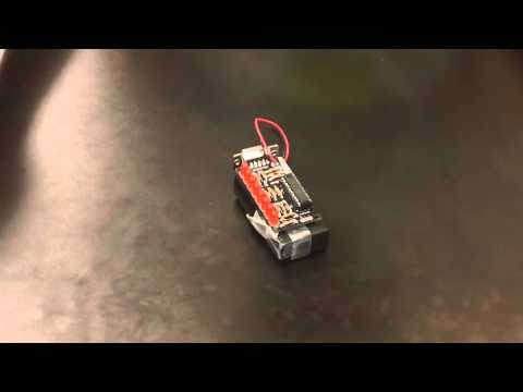

In my first three days at Bluestamp, I built an LED Persistence of Vision device from Adafruit. I learned how to solder on my first day, and was able to connect all of the components (11 resistors, 3 zener diodes, 8 LEDs, 2 battery holder wires, a serial connector, a microcontroller and pin socket) to the printed circuit board. After soldering on these parts to the circuit in the correct orientation and turning on the battery switch, my LED pins lit up in the pre-programmed blinking sequence. The mechanical aspect of my project was done!
The next element to creating my miniPOV device was software. I installed a microcontroller programming software called Avrdude on to my computer, and then connected my device to the computer using a USB-to-serial adapter. The serial connection enables communication between the software and the miniPOV’s microcontroller, so that one can reprogram the miniPOV chip and display customized LED sequences. The process of establishing this serial connection was by far the most tedious and difficult piece of my project. It entailed many cycles of imposing commands in Terminal and searching forums for solutions to failed connection errors. The most persistent error was “AVR device not responding,” meaning that although my miniPOV alone was functional, there wasn’t communication between it and the AVR program on my computer. Troubleshooting involved examining my computer’s serial ports status, manipulating default computer security settings, switching operating systems from OS X to Windows, and running commands as an administrator. Eventually, I was able to connect the device and rewrite the LED code to mypov.c, which spells out my name when the programmed device is waved through the air.
Building this miniPOV device was an incredibly rewarding and helpful experience. I became aware of the uses and functionalities of the individual components soldered to the circuit board, and also the role each part plays in the operation of the circuit as a whole. I also gained lots of troubleshooting experience in the software phase, and became more comfortable with working to resolve Terminal/Command errors on the computer. I’m extremely excited to apply my newly-acquired soldering and troubleshooting skills to my intensive project!
Sakura, you are amazing!
Really cool project
Hello, my name is Mateus I’m from Brazil. I’m making a projetc by hand but i need the program to do that. Could you send it to me please ?