Autonomous RC Car
A repurposed RC car that can either follow a predefined path, or generate its own given a map, starting point, and goal. It uses dead reckoning for navigation, and implements controls systems to make driving commands more accurate.
Engineer
Sahas M
Area of Interest
Electrical Engineering/ Computer Science
School
Monta Vista High School
Grade
Incoming Senior
Reflection
In a perfect world, this autonomous RC car would have worked like a charm. However, compromise after compromise, I finally came to a project I am proud of. It may not have kalman filters, PID control, or be the fastest car in the west, but it did follow and create its own path autonomously. In the future, I hope to get a better car which will allow me to do all the things I hoped to. In addition, I would probably use c++ instead of python because python runs considerably slower.
Electrical/Mechanical
The final project consisted of me controlling the motors manually with a motor driver/h-bridge. My original idea was to solder pins to the existing control board in the car, but when that fried, I had to control them manually. I used a slot-type optocoupler and some cardboard to measure how far the wheels have turned. To measure the direction that the car was pointing towards, I used the Adafruit 9dof sensor which did the absolute orientation measurements for me.
Software
Written in python, and scrappily made, the code is what made the project what it is. In essence, various hander allow controlling and communication to the hardware. One hander establishes interrupts for the encoder, another communicates to the gyroscope, and a final one creates functions to run the motors.
Once these handlers were made, it was on to coding the actual autonomy. I took an existing search algorithm called A* and used it to find the shortest path between two points on a map. Then, I translated the 90 and 45 degree turns into instruction sets that accommodated the car’s turn radius. I did this by creating tangent arcs that intercepted the lines at 2 points, and using that to find hard coordinates to turn to.
PID
One of the major compromises I had to make was using bang bang control instead of PID. PID is the industry standard for control systems because it is accurate, and most accurately simulates how a human would control a car. Unfortunately, to use PID, the steering must be controlled by a servo. If it is controlled by a motor, such as my car, you can only move fully right or fully left.
Kalman Filters
A kalman filter is also the industry standard for filtering fluctuating data. It can quickly find accurate average data even though the input may fluctuate. I was hoping to use it for the gyroscope which was fluctuating about 1%, which for an autonomous car is quite a lot.
These are just links that I found useful in making this project. Most of these, I already had knowledge of, but they are necessary for anybody trying to replicate my project.
Raspberry pi
Setup:
step one: https://howchoo.com/g/ndg2mtbmnmn/how-to-install-raspbian-stretch-on-the-raspberry-pi
step two: put sd card into raspberry pi, boot it up, and connect it to a display
step three: install raspbian (30 mins) then username:pi and pasword:raspberry
step four: enable ssh on the raspberry by going to terminal then typing “sudo raspi-config” go to interfaces and enable ssh
step five: reboot, then from your terminal, ping the raspberry pi. For mac, type “ping raspberrypi.local” in terminal. It should say something along the lines of packets received.
step six: type “ssh [email protected]”
Linux
The terminal is just like your mac’s finder or you pc’s file explorer, just a lot more powerful. I interfaced with the raspberry pi through terminal. Some basics:
ls – lists files in the current directory
cd – ‘opens’ a folder and changes to that directory
clear – clears the terminal
vim – terminal text editor. You may need to install with “sudo apt-get install vim”
Final Milestone: Path Planning & Execution
This final milestone incorporates the movement capabilities of the car with a predefined path. This way, nearly any map with predefined start and end positions can be used on the car. It uses a search algorithm to find a temporary path. The output of that algorithm is then manipulated in a way that it is followable by the car.
How it works
This was by far the most difficult milestone for me to achieve. The first part was easy: finding the shortest path with the ‘A*’ algorithm. It works by ranking the surrounding pixels by desirability, and finding the path of the most ‘desirable’ pixels. This was simple because the problem was already solved (Thanks to Christian Careaga for uploading the python version to the internet).
The hard part was translating the data to something the car could understand and follow. The sharp turns provided by the output of the A* algorithm could not be made by the car. Therefore, I had to use geometry to construct a way to integrate turning radii with the sharp turns.


Above is an image of the path, and the A* output. The white areas are open for the car to move. The grey areas are my paddings from the wall to protect the car. Finally, the black represent places where the car cannot drive.
Inside the image, a green pixel represents the starting position (center of mass of the car). A red pixel similarly represents the ending point.
The redline is the output of the A* algorithm, and it represents the shortest path.
Why I Used It.
The A* Algorithm, created in the early 1970s, was a faster alternative to the more well-known Dijkstra’s Algorithm. It provides a path planning solution for getting around obstacles. I used it to solve the simpler problem of finding a path. There are more possible solutions, but this was the easiest to implement because the code was available online.
How It Works
The algorithm works by ranking the squares around the target. Each square is given a fscore, gscore, and hscore. A fscore ranks the absolute distance between the square and the target. A gscore is the cost of traveling from the start square to the current square. A hscore is a guess to the cost of moving from one square to the goal. Comparing the three scores between squares, and choosing the ones with the lowest score is how the A* algorithm works.

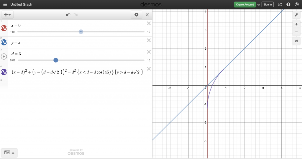
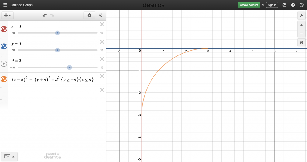
Why I Need it
The A* Algorithm, though it works, does not produce a followable path. The sharp 45 and 90 degree turns cannot be made by the car. Instead, I need to incorporate a turning radius into the path. I attempted this by constructing arcs tangent to the straight lines and incorporating them into the instruction set.
Difficulties
Most of the difficulties came with designing the algorithm. Creating the arcs was not the problem, but detecting the changes in angles was hard. I resorted to saving the generated path into a file, and reading the path to detect angles. In addition, the A* algorithm took 30 seconds to complete, which made it impossible to run in real time. Part of this was the Raspberry pi, but mostly because the raspberry pi does not support CUDA (using the graphics card to run code).
Third Milestone: Control loop
This milestone integrates the BNO055 and the LDR to make a control loop that allows me to direct the car in a specific direction for a specific distance.
This was pure code, and it was written in python on the raspberry pi.
How it Works
Using the BNO055 module, I can get the heading of the car. By reading the heading, and comparing it to the target heading, I can tell whether to turn left or right.
Unfortunately, the car can only move fully left or fully right. This means that it has to oscillate around the target rather than follow it perfectly. This is called bang-bang control. It is not the most accurate, but it works for this purpose.
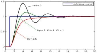
This is where most of the cheapness of the car shows: controls. Most autonomous car use a control called PID, or proportional-integral-derivative. This is the industry standard as it provides the smoothest drive capabiliites.
I couldn’t complete this because it was a DC motor that controlled steering. This means there is no way to control the exact angle that the wheels pointed towards– only fully left or fully right. Hence, the oscillations you see in the videos.
To incorporate PID control, there must be a strong steering servo, like those that are used on $70-$500 hobby cars (not $20 kiddie cars). This way, you can control the angle the wheels point, and it is easier to move in a straight line.
Chassis with servo steering: https://www.amazon.com/Distianert-Electric-Vehicle-Control-Monster/dp/B06Y444YX7/ref=sr_1_5?s=toys-and-games&ie=UTF8&qid=1531501493&sr=1-5&keywords=rc+car
Convert to servo steering: https://www.youtube.com/watch?v=khUMlIVdb48 (keep in mind, the steering mechanism changes between cars. Mine is a gearbox with no exposure or removal).
Second Milestone: Position Estimation
This milestone allow me to interface with the various sensors used to calculate my relative position. I used a LDR to measure wheel rotation and used the absolute orientation sensor in the BNO055 to measure the heading.
How it works
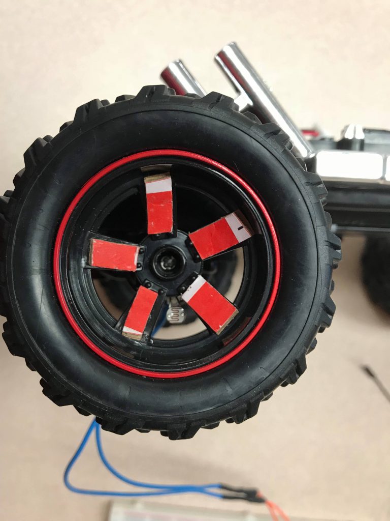
As I mentioned earlier, tracking wheel rotations is a vital part to knowing where you are relative to the starting position. To tackle this problem, I used a Light Dependent Resistor (LDR) to detect if the sensor is behind a spoke or open space. Then, using some calculations, I can indirectly determine the resistance of the LDR, which depends on the ambient light.
Knowing the heading is a much simpler task. Using the BNO055 IMU from adafruit, I can extract the absolute orientation of the car.
The Purpose
An encoder is a appliance that is used to measure how far a wheel has rotated. There are many kinds, but the general idea is that a wheel with deliberately spaced slits/colors goes through a sensor that can detect if the wheel is at a ‘High’ or ‘Low’ position. For this project, I used it for a more accurate estimation of position than multiplying the time of the motor running by a speed constant.
How I implemented it
To simulate the High and Low states, I used a Light Dependent Resistor (LDR) and the spokes of the wheel, which changes the LDR’s resistance depending on if the LDR is behind a spoke or not. However, the raspberry pi 3 cannot directly measure the resistance of the sensor. I had to translate that data into something the Pi could directly measure, such as time. Because the resistance of a circuit directly affects the discharge/charge time of capacitors, I measured the time for the capacitor to discharge enough to set the GPIO to high.
The Math
Because I am measuring time, I need to give the raspberry pi sufficient time to register the time changes. However, if the capacitors take too long to charge/discharge, precious cpu time will be dedicated to waiting for the capacitor to discharge.
Assuming the car moves at 5mps (a high estimate), there is about .125ms between the time it takes for the wheel to move from spoke to spoke. As such, about 15uF capacitance in the capacitors will give the minimum time for a wheel turn to register. 3 33uF capacitors hooked in series gave me 11uF, which was just enough.
The Purpose
In addition to knowing how far your wheels have moved, you need to know what direction you were heading when your wheels were moving. Then, using vector addition, you can find your position. I could not use a regular gyroscope because that only measures angular acceleration. Fortunately, the BNO055 chip from Adafruit possesses the ability to send absolute orientation data.
How it Works
The BNO055 sensor is not like other sensors; it sends more intricate data than a High/Low output. It can send magnetic field, angular acceleration, linear acceleration, and gyroscope data. As a result, I have to communicate with it differently. I used UART, or Universal Asynchronous Receiver-Transmitter. It allows me to send requests and receive data longer than 12 bytes–perfect for absolute orientation data.
First Milestone: Autonomous Control
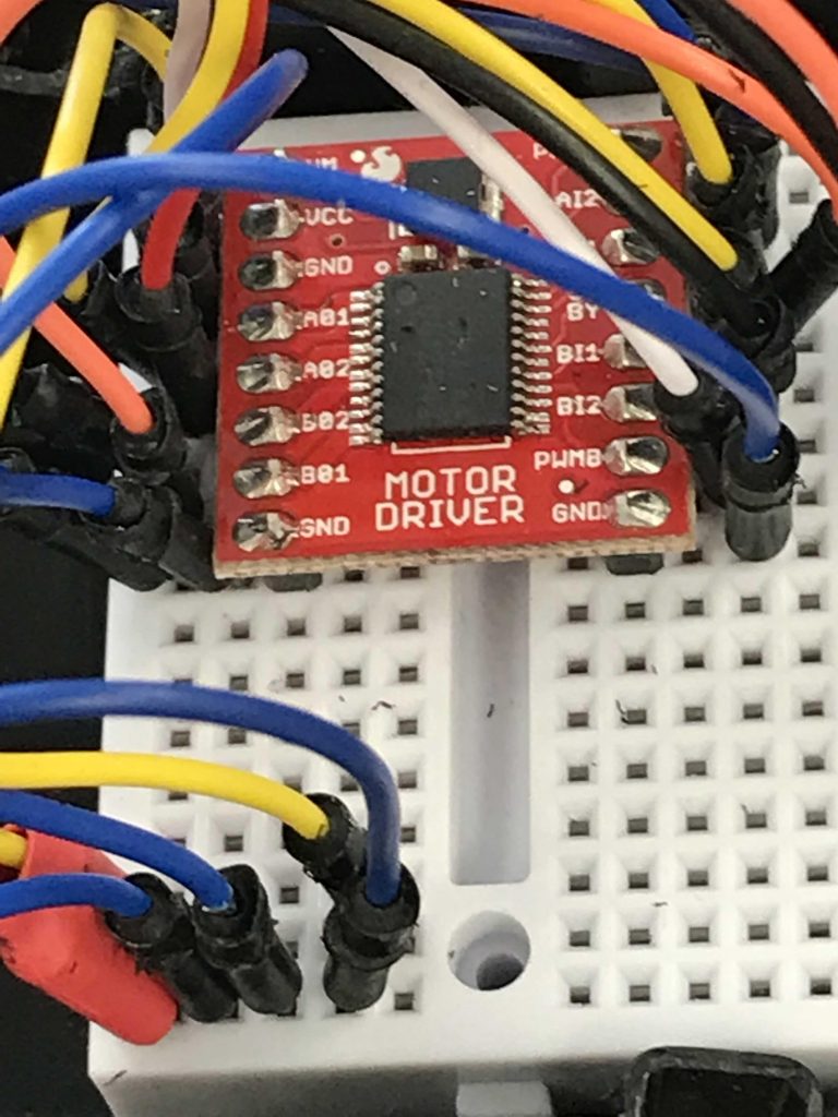
This milestone allows me to control the car 100% programmatically. Requiring no external input, I can tell the motors to move, and make the car move left and right. I use a special motor driver, rated for 3.7V and 1A per motor, to translate the 3.3V/50mA pulses to something more powerful that can run motors.
The Idea
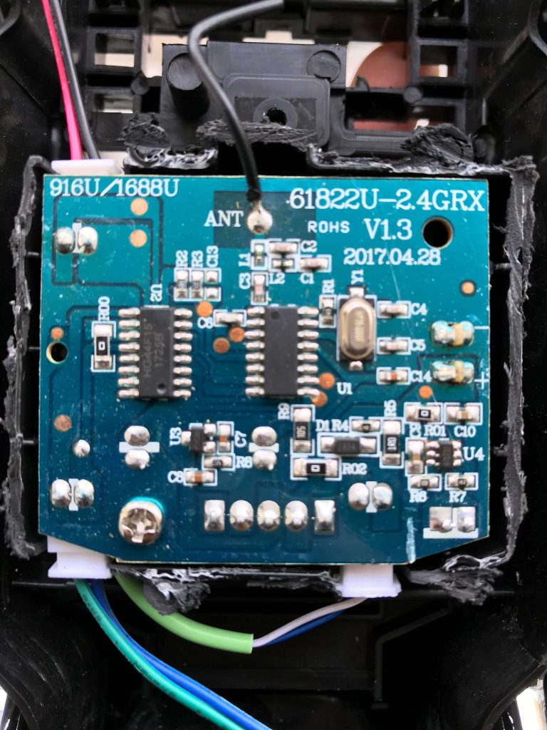
The car is controlled by a micro-controller (the leftmost black rectangle). All it does is send 5V pulses to other components which work together to make the car move. My original idea was to just hijack the micro-controller and simulate the pulses with my own arduino
What Went Wrong
When soldering the ground wire to the battery, I shorted the battery and it could no longer be charged or work. Without the battery, I could not power the motors with sufficient power. This idea was now scrap
The Idea
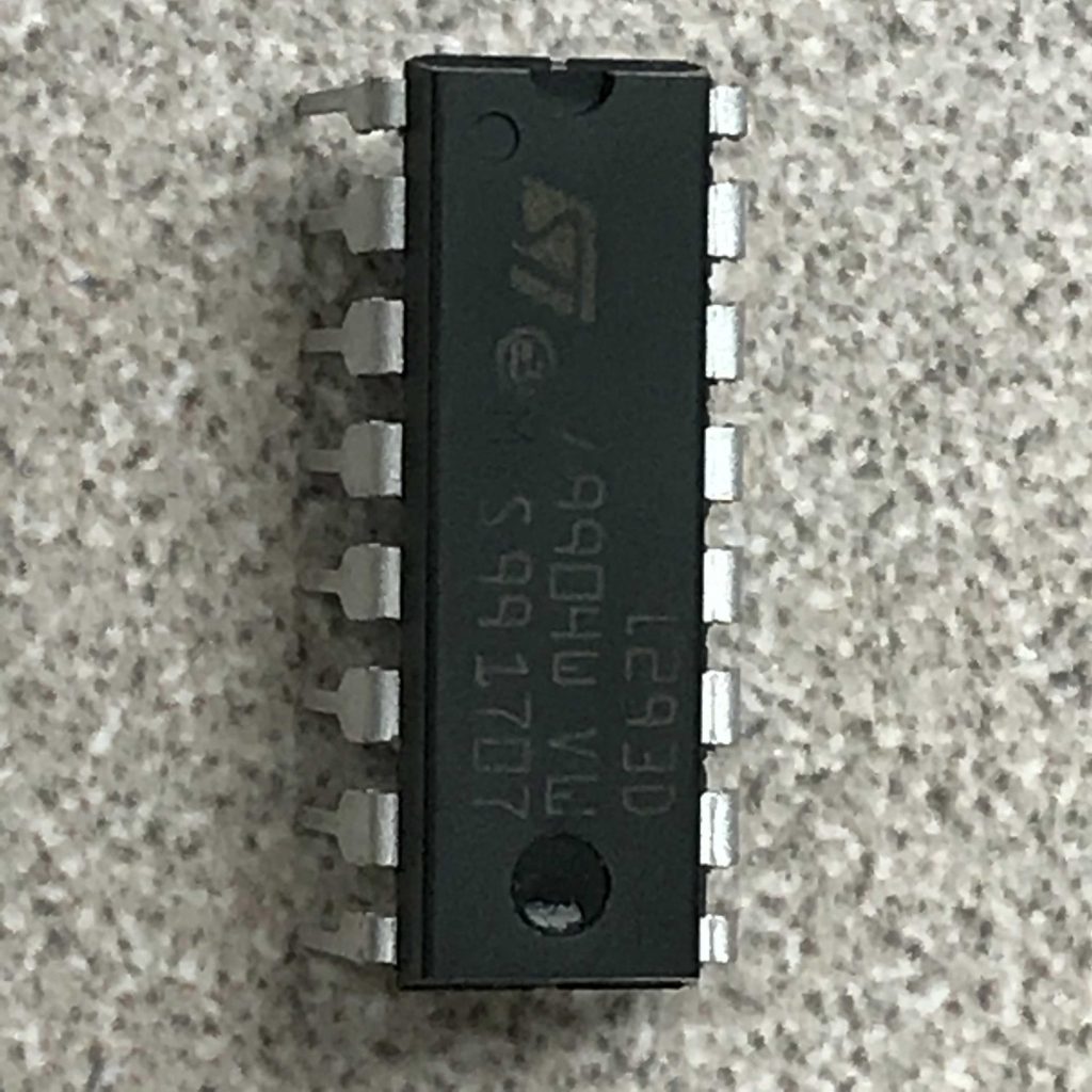
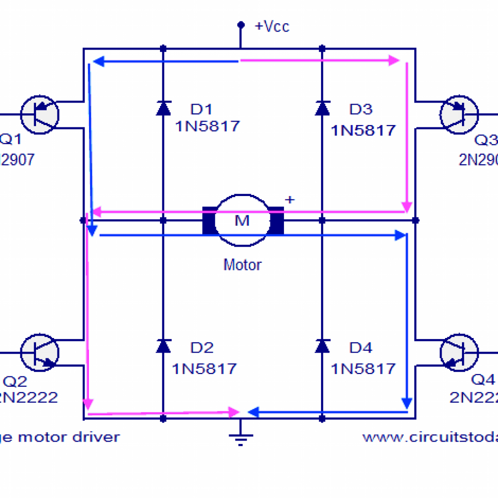
Because I could no longer use the default board, I had to control the motors with a chip called an H-Bridge. It has the ability to switch the direction of current through a motor. When current goes in a different direction, the motor spins in a different direction. When I control the pins of the h bridge, I can control the motors
What Went Wrong
The L293D h bridge specifically did not work with the motors. Given 3.3V, the motors have a stall current of 800mA. According to the L293D datasheet, that specific chip could only output 600mA. This was not going to be enough for the motor. I attempted it anyways, hoping the 1.2A burst was going to allow the car to start then run on 600mA. However, the chip burned in the process, and I had to find an alternative.
Final Solution
To solve the problem of the h bridge not working, I had to find another h bridge motor drive that could handle the voltage and current of the motors. Finally, the TB6612FNG from sparkfun had the voltage output and current necessary to run my motors. My next problem was a battery. Lucklily, bluestamp had a few 3.7V 600mAh Li Ion batteries that would run the car for about 45 minutes on a charge.
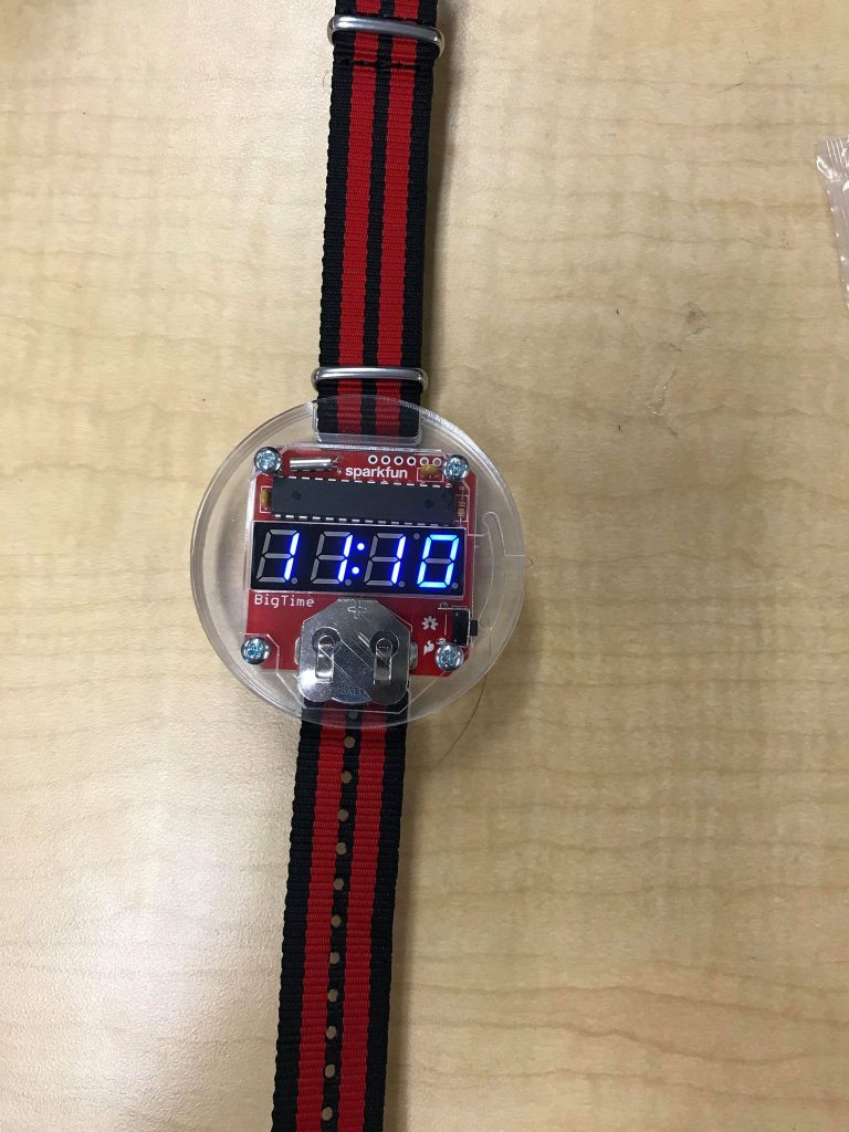
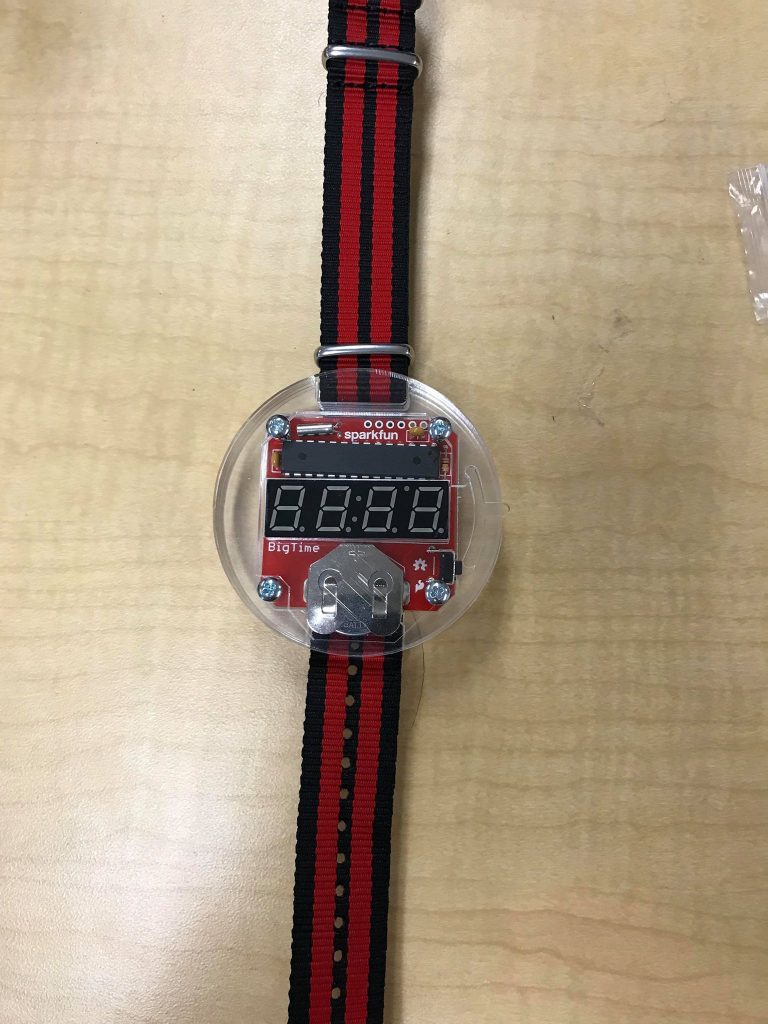
Starter Project
How it Works
The brain of the watch is the micro-controller located above the display. It runs pre-deployed code and controls the display through its pins located above and below the controller. Most of the pins from the micro-controller control the display. 14 of the 16 pins on the display control which LEDs light up, while the other two are negative and positive terminals that supply the power to the display. Timing is controlled by an oscillating crystal. Inside of it is a quartz crystal that vibrates at 32kHz which the micro-controller can use as a way to track time passed. Two 0.1µF capacitors are used to filter AC noise caused by inconsistent voltages within the circuit and contribute to the longevity of the project. The entire watch is controlled by a 3v coin battery located at the bottom of the watch. Power is given to the micro-controller at all times to keep track of time, but the display only lights up when the switch is pressed when the micro-controller receives a 3v input from the battery.