Independent Modifications
For my first independent modification, I used the XBee radio modules to make the communication between my own finger motions and my 3D printed hand wireless. During this modification, my computer programming skills were challenged as I delved into a deeper complexity of Arduino coding. I split this modification into two steps to make it easier to work my way up to the larger challenge.
Step 1
My first challenge was to learn how to program and use the XBees. I downloaded that XCTU Software and played around with its functions. For this step, my goal was control LEDs using the XBee Modules
Step 2
My second challenge was to figure out how to send unique signals from each flex sensor to its corresponding servo. Since the XBee modules would simply transmit any signal given or received, I constructed a pattern to distinguish between the 4 sensors and servos. I also had to tackle the challenge of the Xbees being a serial modules. My goal was to successfully control the motion of my 4 servos as I manually imitated the signals sent by the flex sensors.
Future Goals: I would like to continue working on this project, and possibly integrate my interest in Mandarin into the programming aspect of my robotic hand. A potential modification is to use my 3D hand to show the hand gestures for each of the numbers in Mandarin, depending on the user input.
My final Arduino codes for this independent modification are shown below. The first code was programmed into the Arduino with the Coordinator XBee Module. The second code was for the End Point Xbee Module.
Coordinator Module
#include <Servo.h>

String servoPosString1 = "";
String servoPosString2 = "";
String servoPosString3 = "";
String servoPosString4 = "";

const int flexPin = A1;
const int flexPin2 = A2;
const int flexPin3 = A3;
const int flexPin4 = A4;

void setup() {

     Serial.begin(9600);
}

void loop() {

//setting variables
  int flexPostion;
  int servoPostion;

  int flexPosition2;
  int servoPostion2;

  int flexPosition3;
  int servoPostion3;

  int flexPosition4;
  int servoPostion4;

//analog readings
  flexPosition = analogRead(flexPin);
  flexPosition2 = analogRead(flexPin2);
  flexPosition3 = analogRead(flexPin3);
  flexPosition4 = analogRead(flexPin4);

//mapping servo position
  servoPosition = map(flexPosition, 400, 600, 0, 180);
  servoPosition = constrain(servoPosition, 0, 180);

  servoPosition2 = map(flexPosition2, 300, 700, 0, 180);
  servoPosition2 = constrain(servoPosition2, 0, 180);

  servoPosition3 = map(flexPosition3, 300, 700, 0, 180);
  servoPosition3 = constrain(servoPosition3, 0, 180);

  servoPosition4 = map(flexPosition4, 400, 900, 0, 180);
  servoPosition4 = constrain(servoPosition4, 0, 180);

  servoPosition += 1000;
  String servoPosString1 = String(servoPosition);
  servoPosString1.concat('>');
  //concat function adds the '>' symbol to the String "servoPosString1"
  Serial.print(servoPosString1);

  servoPosition2 += 2000;
  String servoPosString2 = String(servoPosition2);
  servoPosString2.concat('>');
  Serial.print(servoPosString2);

  servoPosition3 += 3000;
  String servoPosString3 = String(servoPosition3);
  servoPosString3.concat('>');
  Serial.print(servoPosString3);

  servoPosition4 += 4000;
  String servoPosString4 = String(servoPosition4);
  servoPosString4.concat('>');
  Serial.print(servoPosString4);
}
End Route Module
#include <Servo.h>

Servo servo1, servo2, servo3, servo4;

int myData;
int servoPosition;
int incomingByte;
String inString = "";

void setup() {

     Serial.begin(9600);

     servo1.attach(3);
     servo1.write(0);

     servo2.attach(11);
     servo2.write(0);

     servo3.attach(6);
     servo3.write(0);

     servo4.attach(5);
     servo4.write(0);
}

void loop() {

  if(Serial.available() > 0) {

    while (Serial.available() > 0) {

      myData = Serial.read();

      if (isDigit(myData)) {
         //convert the incoming byte to a char and add it to the string
         inString += (char)myData;
         }

      if (myData == '>') {
         incomingByte = inString.toInt();
         //clear the string for new input:
         inString = "";
         }

    }

    if (incomingByte >= 1000 && incomingByte < 1180) {
       incomingByte -= 1000;
       servo1.write(incomingByte);
       }

    if (incomingByte >= 2000 && incomingByte < 2180) {
       incomingByte -= 2000;
       servo2.write(incomingByte);
       }

    if (incomingByte >= 3000 && incomingByte < 3180) {
       incomingByte -= 3000;
       servo3.write(incomingByte);
       }

    if (incomingByte >= 4000 && incomingByte < 4180) {
       incomingByte -= 4000;
       servo4.write(incomingByte);
       }
  }
}
Step 2
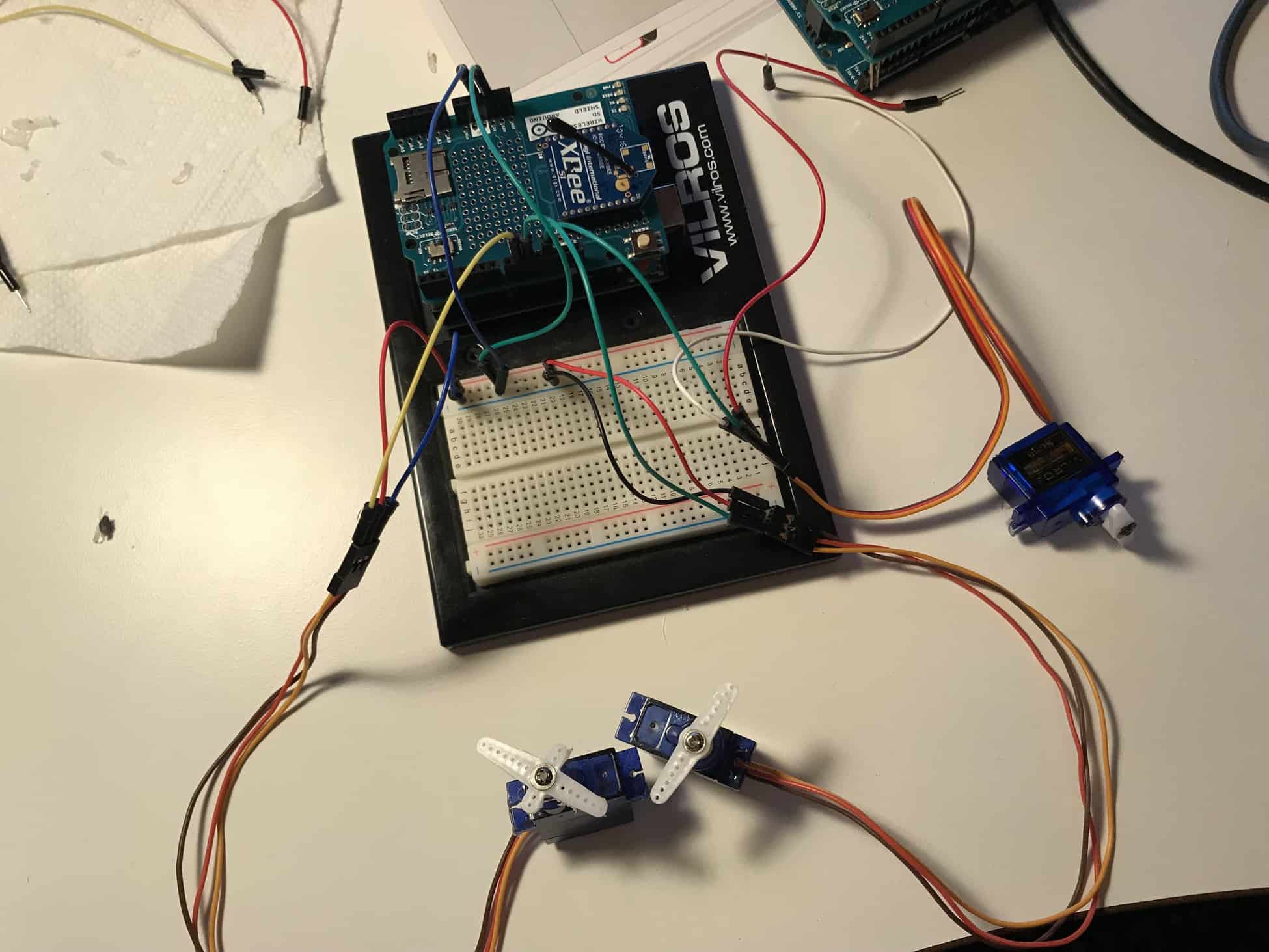
My second goal was to remotely control the rotation of four different servos by sending a unique signal to each one. One of the challenges I would eventually have to solve was how my second Arduino & XBee would distinguish between the four signals sent by my first Arduino & XBee, and correctly transmit the signals to the appropriate servo. I solved this problem by creating a unique, standardized pattern for each signal sent by my coordinator XBee module. The details of my code are explained below (Numerical Range section). When testing, I also encountered power distribution issues once again. Since I was using four servos on one Arduino, I realized that my current 9V battery was not enough to power the entire circuit. I switched to the power bank I was using for my project, which solved the problem. The difference between these power sources was that the power bank provided more current than the 9V battery, allowing all the servos to function. Furthermore, the third servo I was using was not working well, so I could only test servo1, servo2, servo4.
[Code Explanation] Signal Analysis: One challenge I faced was the fact that my end-route XBee module could not read my manual input as an integer, but as a string instead. On top of that, my receiving module could only read my input one digit at a time. Instead of reading my 4-digit input as “1090“, it would read it as “1“, “0“, “9“, “0” and respond to each single digit. This was because my code would read my inputted signal through a serial (think series) read. The first part of my Arduino code (the while loop), was where I joined each individual character of my input into a string consisting of the entire 4-digit input. I added a “>” to my input, which my code would read as the stopping point for my string. Once I created the appropriate 4-digit string, I used the toInt function to turn the string into an integer. This would allow me to eventually do the arithmetic manipulation as described by the Numerical Range part of my code explanation.
[Code Explanation] Numerical Range: I needed a standardized format for the signals sent by my coordinator module. This way, my second Arduino would be able to correctly transmit the four signals sent by the first XBee to the appropriate servos. Since I was sending a manual signal from one XBee to the other, I only concerned myself with the receiving portion of this challenge. To do this, I assigned a certain numerical range for each servo. Since servos can rotate from 0°-180°, which is a 1-digit to 3-digit range, I standardized my transmission signals to a 4-digit value. Thus, servo1 would respond to a signal within the range of 1000-1180, servo2 would respond to 2000-2180, etc. (see code below). Therefore, the first digit of each signal would describe which servo should react. Since my Arduino would have to test for each of these ranges, I put them in if statements, once the incoming signal was analyzed. To rotate the servos, I wrote a simple arithmetic code which subtracted 1000 from the signal inputted for servo1, 2000 for servo2, etc. This would give a value from 0°-180° to which the servo would rotate to.
Arduino Code
Testing Manual Inputs w/ Four Servos
#include <Servo.h>

Servo servo1, servo2, servo3, servo4;

int myData;
int servoPosition;
int incomingByte;
String inString = "";

void setup() {

     Serial.begin(9600);

     servo1.attach(9);
     servo1.write(0);

     servo2.attach(10);
     servo2.write(0);

     servo3.attach(11);
     servo3.write(0);

     servo4.attach(12);
     servo4.write(0);
}

void loop() {

  if(Serial.available() > 0) {

    while (Serial.available() > 0) {

      myData = Serial.read();

      if (isDigit(myData)) {
         //convert the incoming byte to a char and add it to the string
         inString += (char)myData;
         }

      if (myData == '>') {
         incomingByte = inString.toInt();
         //clear the string for new input:
         inString = "";
         }

    }

    if (incomingByte >= 1000 && incomingByte < 1180) {
       servoPosition = incomingByte - 1000;
       servo1.write(servoPosition);
       }

    if (incomingByte >= 2000 && incomingByte < 2180) {
       servoPosition = incomingByte - 2000;
       servo2.write(servoPosition);
       }

    if (incomingByte >= 3000 && incomingByte < 3180) {
       servoPosition = incomingByte - 3000;
       servo3.write(servoPosition);
       }

    if (incomingByte >= 4000 && incomingByte < 4180) {
       servoPosition = incomingByte - 4000;
       servo4.write(servoPosition);
       }
  }
}
Step 1
My first step to achieving this modification was to learn how the XBee radio module wireless communication worked. After purchasing the necessary components for my modification, including the XBees, Arduino Proto Shields, and XBee Explorers, I utilized manuals and online tutorials to teach myself the fundamentals of wireless communication. I downloaded the XCTU program, which allowed me to configure my two XBees. I learned how to connect the radio modules to this program, and change their settings so I could receive and send messages between the XBees. I used the console working mode to send frames from my coordinator to my end point module. My first goal was to write a simple code turning an LED on and off through wireless communication. After first confirming that my XBee modules were configured correctly, I wrote a simple Arduino code displayed below which allowed me to remotely manipulate the LED light switch. I took my experimentation a step further, and tried to determine the maximum distance the two XBees could communicate with each other. The video of this test is displayed on the right.

Arduino Code
Wirelessly Controlling a LED Light Switch w/ XCTU
int myData = 0;
int const ledPin = 13;

void setup() {

     Serial.begin(9600);
     pinMode(ledPin, OUTPUT);
}

void loop() {

  if (Serial.available() > 0) {
      myData = Serial.read();

      if (myData == '1') {
         digitalWrite(ledPin, HIGH);
         Serial.print(myData);
      }

      if (myData == '2') {
         digitalWrite(ledPin, LOW);
         Serial.print(myData);
      }

      else {
         Serial.print(myData);
      }
  }
}
Demo Night Presentation
Important Links
Bill of Materials (BOM): price, ordering site links, and quantities for each and every material used
Build Plan: plan for milestones, guide for build process
3D Printed Hand: STL files for printing of 3D hand
Final Arduino Code: final updated code
Reflection
Erik once asked us, “Last year did you ever think you could build such a project in a year’s time?”
And I can honestly say “No”. The amount of technical knowledge I have gained in coding, circuitry, and mechanical building has been incredible. I can still remember walking into BlueStamp my first day, struggling to understand the difference between male-male and female-male jumper wires. After only 6 weeks I have learned how to solder correctly, create schematics, program with Arduino, use capacitors, voltage regulators, and potentiometers, and so much more. This program has encouraged me to take initiative of my own challenges and setbacks; unlike school where I could immediately receive help from a teacher, I had to do my own testing and research to solve the issues I encountered. Through this “independent” mindset, I was able to become an expert in all the technical components in my project. Furthermore, this program pushed me to continue persevering even when I was exhausted and exasperated. At one point, I was struggling with servo issues for weeks in a row. However, the prospect of having a fully functioning 3D robotic hand motivated me to persist and continue troubleshooting. In the end, pushing through my setbacks proved to be quite a rewarding experience. With a supportive group of mentors and peers, this summer has opened my eyes to the world of mechanical, electrical, and computer engineering.
Final Milestone
For my final milestone I demonstrated my completed project: using the glove, I can mirror the motion of my own fingers to those of my 3D printed hand.
In my third milestone, I showed how moving my fingers within my glove moves the servos. Since this milestone I have been working on installing my 4 servos into my robotic hand, as well as using fishing wire to connect my 3D printed fingers to each corresponding servo. In the beginning, I naively believed that I was finished with the harder aspects of my project, especially since I had spent the last few weeks on refining my electrical components and circuits. However, these stages provided some of the most challenging obstacles and roadblocks.
Installing the servos within my robotic hand was relatively easy: all it required were screws and a screwdriver. In order to fit my servos within their respective locations, I had to take off the servo horns. When I attached the horns back I attached them in a random manner, unintentionally creating new challenges for the future. The next step was attaching the servos to my circuit. To minimize wiring issues, I decided to rewire my servo circuit into a more simple design. I removed all unnecessary wires and connected the servo pins directly into my breadboard (before, I used extra wires to secure a connection).
My last step was arguably the hardest aspect of my entire project: wiring and tensioning my 3D fingers to each servo. At first, I used two separate wires to control the movement of each finger: one to fully extend and one to flex. After an entire day of testing, I determined an efficient method of wiring my servos: first tension the string for my extension, then rotate my servo horn 90° and tension the string for my flexing motion afterwards. Unfortunately, as I began testing my servos with my glove, the flexing motion of my fingers was choppy. In addition, my servos would move to random positions immediately after connecting my circuit to power. I ended up having several issues with my project–from bad wiring to unexpected servo rotations–that took me multiple days to resolve.
To increase the smoothness of my flexing motion, I decided to use 1 long string of wire instead of 2 separate wires. Fortunately, this change provided a smoother motion. Currently, my fingers work similar to the motion of a pulley. I tried various methods to solve the problems with my servo rotations, including trying to integrate capacitors, potentiometers, or even resistors within my circuit. Eventually, I checked various sections of my circuit to try to find any possible wiring issues. I noticed that I still had my voltage regulator connected. Since this component was not crucial for the basic workings of my circuit, I decided to test my circuit without it. In addition, I was currently only using 7.2V compared to 9V before. I theorized that I did not need my voltage regulator anymore. After trying my circuit without the voltage regulator, my third servo began to run smoothly. Every time I changed a component within my 3D hand I was forced to adjust and redo each of my servos, which proved to be an arduous task over the course of these past few weeks.
Future Goals: In the future I would like to incorporate different modifications into my project. My first modification will be making the communication between the flex sensors and 3D robotic hand wireless using XBee modules.
Evolution of Breadboard Circuit (Hover)
Initial Breadboard Circuit
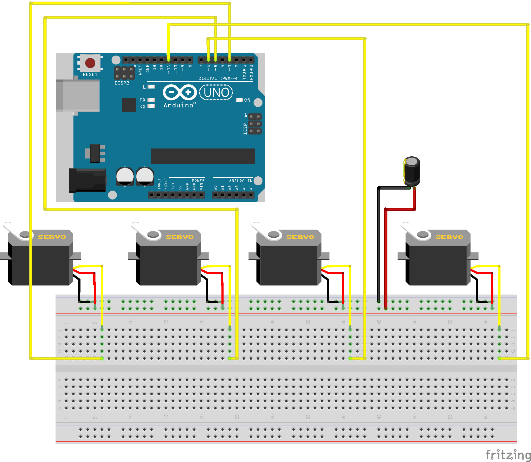
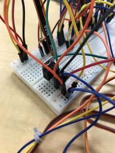
Initially, I had very little knowledge about circuitry and the electrical components of my project. I tended to use a lot of unnecessary wires due to my inexperience. In the beginning, I used the terminal strips for all my connections resulting in a confusing mass of wires.
Redesigned Breadboard Circuit
Throughout my project, I continue to iterate my design; my breadboard circuit evolved over the course of these past 6 weeks. As I gained more knowledge about general circuitry and the specific electrical components of my project, I was able to condense my circuit into a few vital wires. In addition, I used the power strips on my breadboard to directly connect to my servo pins, instead of using the terminal strips.
Arduino Code
#include <Servo.h>

Servo servo1, servo2, servo3, servo4;

const int flexPin = A1;
const int flexPin2 = A2;
const int flexPin3 = A3;
const int flexPin4 = A4;

void setup() {
// put your setup code here, to run once:

     Serial.begin(9600);

     servo1.attach(3);
     servo1.write(0);

     servo1.attach(11);
     servo1.write(0);

     servo1.attach(6);
     servo1.write(0);

     servo1.attach(5);
     servo1.write(0);

}

void loop() {
// put my main code here, to run repeatedly:

     // setting variables
     int flexPosition;
     int servoPosition;

     int flexPosition2;
     int servoPosition2;

     int flexPosition3;
     int servoPosition3;

     int flexPosition4;
     int servoPosition4;

     // analog readings
     flexPosition = analogRead(flexPin);
     flexPosition2 = analogRead(flexPin2);
     flexPosition3 = analogRead(flexPin3);
     flexPosition4 = analogRead(flexPin4);

     // mapping servo position
     servoPosition = map(flexPosition, 400, 600, 0, 180);
     servoPosition = constrain(servoPosition, 0, 180);

     servoPosition2 = map(flexPosition2, 300, 700, 0, 180);
     servoPosition2 = constrain(servoPosition2, 0, 180);

     servoPosition3 = map(flexPosition3, 300, 700, 0, 180);
     servoPosition3 = constrain(servoPosition3, 0, 180);

     servoPosition4 = map(flexPosition4, 400, 900, 0, 180);
     servoPosition4 = constrain(servoPosition4, 0, 180);

     // changing servo
     servo1.write(servoPosition);
     servo2.write(servoPosition2);
     servo3.write(servoPosition3);
     servo4.write(servoPosition4);

     Serial.print(flexPosition);
     Serial.print("  ");
     Serial.println(servoPosition);

delay(20);
}
Modifications: Due to my servos randomly moving to various positions when connected to power, I decided to write all my servos to 0° in my setup function. This way, all my servos would correspond to upright finger positions each time I connected my circuit to power.
Final Breadboard Circuit
Third Milestone
For my third milestone I decided to showcase my glove working, specifically illustrating how moving my gloved fingers corresponds to rotations in my servos.
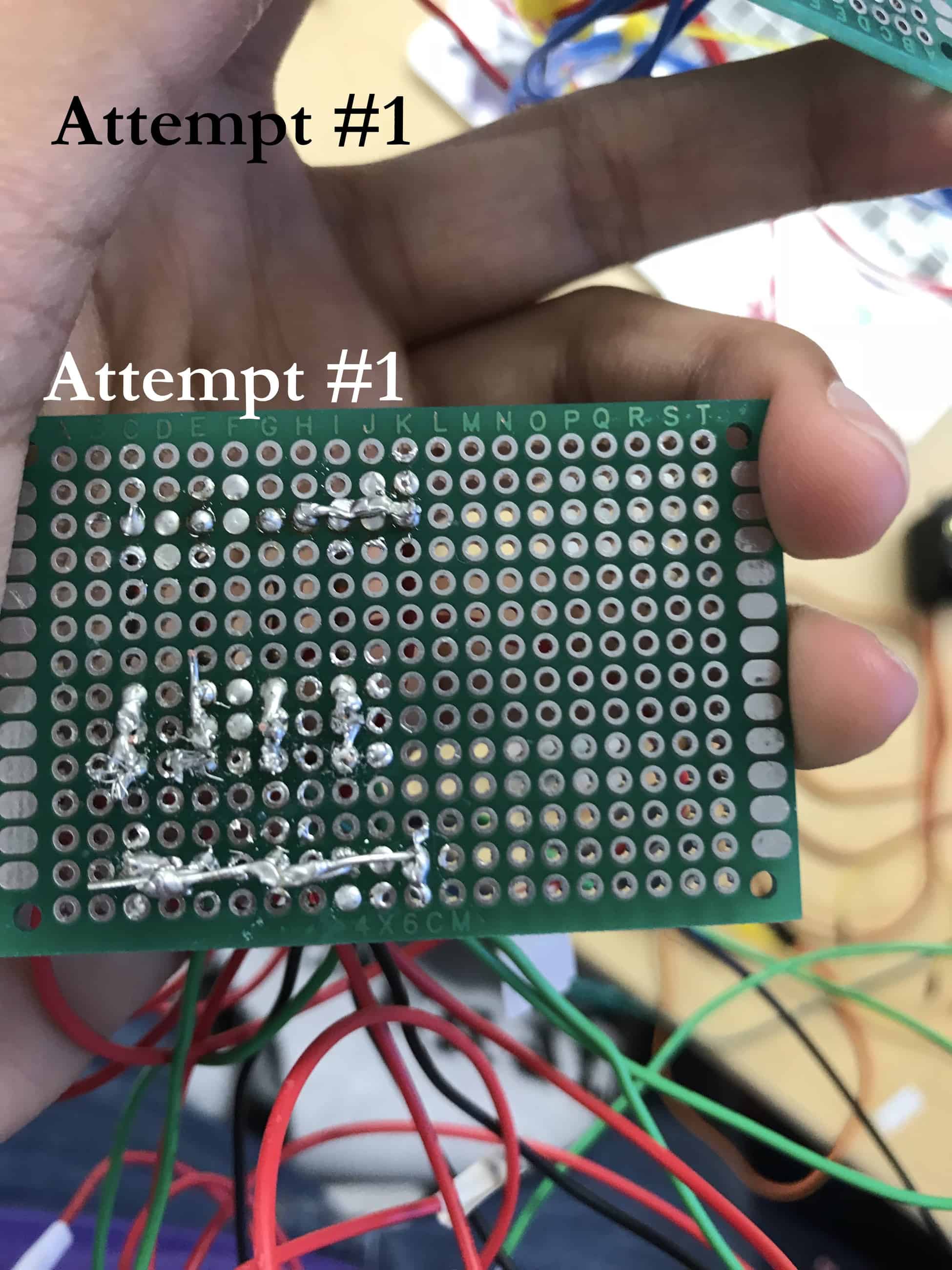
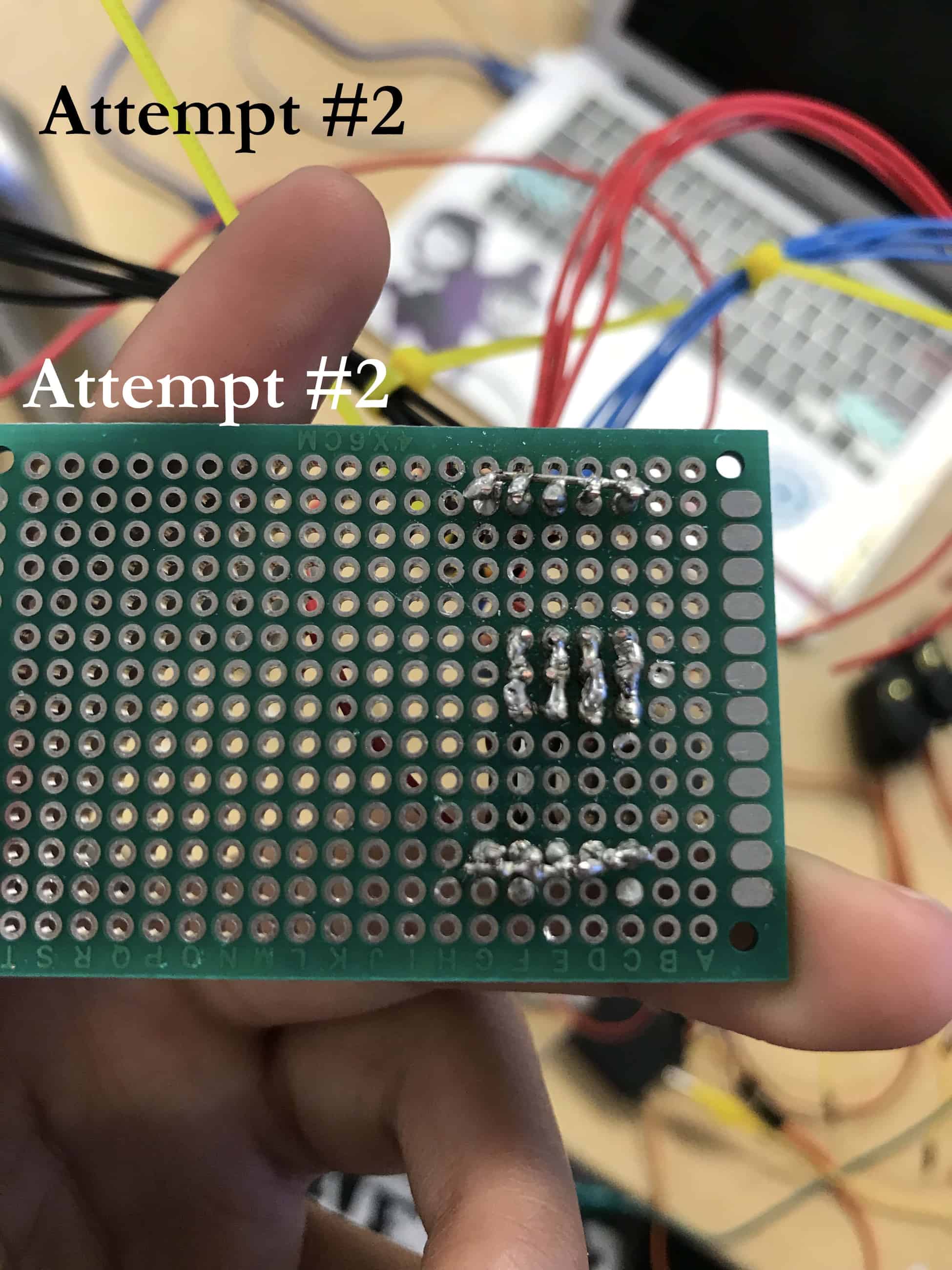
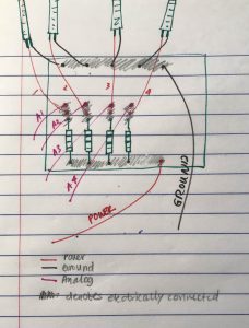
I have made many modifications to my project since my second milestone. My first step was to transfer all of the wiring for my flex sensors to a blank PCB. At first I tried copying an online schematic onto my PCB. However, their configuration was different than that of my breadboard circuit. Trying to reference both the online schematic and my breadboard circuit quickly became confusing; instead I decided to create my own schematic. After realizing the position of my resistor did not matter since I was creating a series circuit, I was able to create a rough schematic sketch. I had various challenges while trying to solder my electrical components as well. To create a connection between my power wire, resistor, and analog wire, I had to solder across 3 joints. I struggled with determining an efficient way to purposely solder multiple joints together; most times, the solder would simply clump onto one of the pins. My first solder job was very messy and did not work due to several cold solder joints and poor solder connections. At first I tried resoldering a few pins, but eventually decided it was worth the time and risk to start fresh and solder a new set of wires/resistors onto a new PCB. This took me a day’s worth of time to restart my soldering job.
After I finished, I began testing my PCB with my flex sensors and servos. To protect the delicate ends of my sensors, I attached clinchers to the ends of my sensors. However, once I attached my sensors in a circuit, my 4th servo stopped rotating. I learned how to use a multimeter to check the voltage across each connection. This method helped me find the root of my connection issues efficiently and quickly. At first, I believed it was a problem with the ground wire connection to my 4th sensor; however, after extensive troubleshooting and testing with the multimeter, I realized that my 4th power wire connection was faulty. After resoldering this cold joint, I was able to successfully run all my servos smoothly.
The final aspect of this milestone was attaching my flex sensors to my glove. There were various methods of sticking my sensors onto my glove. I chose to use long strips to tape the sensors along the length of each glove finger. I cut small triangles at each of my finger joints, to accommodate the bend of my fingers. The final step was sticking my PCB to the middle of my glove.
Future Goals: My goal for my final milestone is to install my servos into my robotic hand, and have a fully functioning robotic hand.
Final PCB Circuit

Arduino Code
#include <Servo.h>

Servo servo1, servo2, servo3, servo4;

const int flexPin = A1;
const int flexPin2 = A2;
const int flexPin3 = A3;
const int flexPin4 = A4;

void setup() {
// put your setup code here, to run once:

     Serial.begin(9600);

     servo1.attach(10);
     servo2.attach(11);
     servo3.attach(6);
     servo4.attach(5);

}

void loop() {
// put my main code here, to run repeatedly:

     // setting variables
     int flexPosition;
     int servoPosition;

     int flexPosition2;
     int servoPosition2;

     int flexPosition3;
     int servoPosition3;

     int flexPosition4;
     int servoPosition4;

     // analog readings
     flexPosition = analogRead(flexPin);
     flexPosition2 = analogRead(flexPin2);
     flexPosition3 = analogRead(flexPin3);
     flexPosition4 = analogRead(flexPin4);

     // mapping servo position
     servoPosition = map(flexPosition, 400, 900, 0, 180);
     servoPosition = constrain(servoPosition, 0, 180);

     servoPosition2 = map(flexPosition2, 300, 700, 0, 180);
     servoPosition2 = constrain(servoPosition2, 0, 180);

     servoPosition3 = map(flexPosition3, 400, 900, 0, 180);
     servoPosition3 = constrain(servoPosition3, 0, 180);

     servoPosition4 = map(flexPosition4, 400, 900, 0, 180);
     servoPosition4 = constrain(servoPosition4, 0, 180);

     // changing servo
     servo1.write(servoPosition);
     servo2.write(servoPosition2);
     servo3.write(servoPosition3);
     servo4.write(servoPosition4);

     // printing information
     Serial.print("sensor 1: ");
     Serial.print(flexPosition);
     Serial.print(" servo 1: ");
     Serial.println(servoPosition);

     Serial.print("sensor 2: ");
     Serial.print(flexPosition2);
     Serial.print(" servo 2: ");
     Serial.println(servoPosition2);

    //Serial.print("sensor 3: ");
    //Serial.print(flexPosition3);
    //Serial.print(" servo 3: ");
    //Serial.println(servoPosition3);

    //Serial.print("sensor 4: ");
    //Serial.print(flexPosition4);
    //Serial.print(" servo 4: ");
    //Serial.println(servoPosition4);

delay(20);
}
Modifications: When I was troubleshooting my programming issues, I decided to use the serial monitor to analyze the readings of my flex sensor position and servo position. I used the Serial.print function to print these values on my serial monitor. In addition, my mapping values changed due to multiple tests of my servo rotations.
Second Milestone
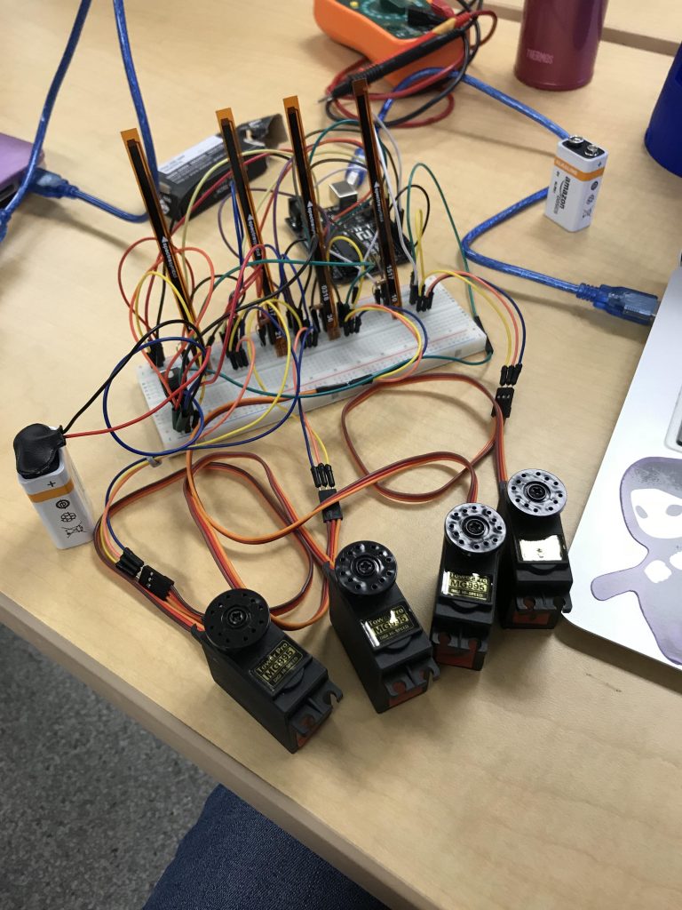
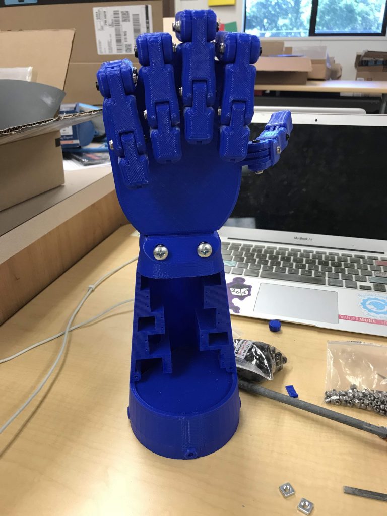
For my second milestone I decided to showcase 4 sensors and servos working smoothly, as well as a fully assembled 3D printed hand and base.
I chose to show 4 sensors and servos working because getting all components to work smoothly took me approximately 4-5 days to troubleshoot. In the beginning, I could run 2 sensors and servos smoothly from just my arduino; however, when I connected all 4, the last 2 sensors did not rotate or run at all. Initially, I tried troubleshooting by checking–and re-checking–my arduino code, as well as rewiring my circuit multiple times. However, my code was exactly the same for each sensor and servo, so I easily determined it could not be a programming issue. I even tried playing around with the parameters of my map(); function to try to get a little bit of movement from my last 2 sensors. In addition, even after rewiring my circuit 3 times, on different breadboards, I still wasn’t getting any rotation from my last 2 sensors. Eventually, I decided to look elsewhere to troubleshoot.
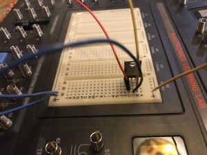
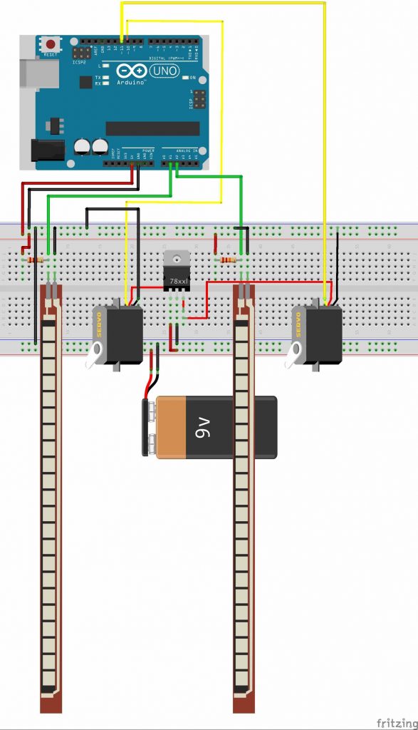
After researching the specifications of my servos online, I realized that I probably wasn’t providing enough power to my servos. Each servo drew approximately 4.8-6.6V and 170mA of current. However, my arduino only supplied maximum 5V and 40mA from each digital pin (definitely not enough to power 4 servos). Therefore I determined I needed an external power source to provide more voltage and current to all my servos. Initially, I simply connected a 9V battery to the power strip of my breadboard, and drew a ground wire from my arduino to the power strip. Instead of working smoothly all of my servos began twitching and rotating uncontrollably, completely bypassing all of the code I uploaded to my arduino. After multiple trials, I realized that I was providing too much voltage to my circuit, and potentially could have seriously damaged my electrical components. To combat this problem, I tried integrating a voltage regulator within my circuit. This way, I would reduce the inputted voltage within my circuit, but still provide enough current for all 4 servos to work. Since I had no prior knowledge of how to use a voltage regulator, I spent a night learning how to properly integrate and connect it within a simple circuit. I applied this knowledge the next day to attach my voltage regulator correctly to the other components in my circuit.
Unfortunately, even with the voltage regulator my last 2 servos were not working at all. Eventually I decided to power my flex sensors with my arduino, and my servos with my 9V. Since my sensors did not require a lot of power to run, this would be an efficient distribution of my power supply. I configured my circuit such that my voltage regulator would be used to decrease the voltage from my 9V battery. Finally, all 4 sensors and servos began to work. Again, I tried different values for my map(); function until I got the rotation I desired.
In addition to problems with my circuit, I experienced a few challenges while building my 3D printed hand. In the beginning, I began screwing in each finger to the palm without considering the orientation of the screws and nuts. However, I realized that each finger attached in a specific orientation, as I began encountering challenges fitting screws in between each finger. As a reference, I drew a detailed diagram of the bolt-nut orientation. Moreover, while trying to screw in the hand to the base I realized that the screws I had ordered were too short to fit a nut on the other side. Instead, I used a larger screw and hot-glued the sharp end (for saftey reasons only) to keep the hand secure on the base. This fastening method is only temporary, and I will eventually trade them out for correctly-sized screws.
Future Goals: My goal for the next milestone is to solder all my electrical components onto a PCB, sew my sensors onto my glove, and show that my servos rotate smoothly with the glove apparatus.
Circuit Schematic (2 Sensors & Servos)
First Milestone

Arduino Code
#include <Servo.h>

Servo servo1, servo2, servo3, servo4;

const int flexPin = A1;
const int flexPin2 = A2;
const int flexPin3 = A3;
const int flexPin4 = A4;

void setup() {
// put your setup code here, to run once:

     Serial.begin(9600);

     servo1.attach(10);
     servo2.attach(11);
     servo3.attach(6);
     servo4.attach(5);

}

void loop() {
// put my main code here, to run repeatedly:

     // setting variables
     int flexPosition;
     int servoPosition;

     int flexPosition2;
     int servoPosition2;

     int flexPosition3;
     int servoPosition3;

     int flexPosition4;
     int servoPosition4;

     // analog readings
     flexPosition = analogRead(flexPin);
     flexPosition2 = analogRead(flexPin2);
     flexPosition3 = analogRead(flexPin3);
     flexPosition4 = analogRead(flexPin4);

     // mapping servo position
     servoPosition = map(flexPosition, 400, 700, 0, 180);
     servoPosition = constrain(servoPosition, 0, 180);

     servoPosition2 = map(flexPosition2, 200, 500, 0, 180);
     servoPosition2 = constrain(servoPosition2, 0, 180);

     servoPosition3 = map(flexPosition3, 400, 700, 0, 180);
     servoPosition3 = constrain(servoPosition3, 0, 180);

     servoPosition4 = map(flexPosition4, 200, 500, 0, 180);
     servoPosition4 = constrain(servoPosition4, 0, 180);

     // changing servo
     servo1.write(servoPosition);
     servo2.write(servoPosition2);
     servo3.write(servoPosition3);
     servo4.write(servoPosition4);

delay(20);
}
My first milestone was showcasing two flex sensors and servos working efficiently and smoothly. As the user bends the flex sensor, the servo begins rotating to a maximum of 180°. Additionally, the more the user bends the sensor, the faster each servo rotates.
As of now, I have been using an arduino, breadboard, wires, flex sensors, resistors, and servos. Since I did not have the 3D printed materials yet, I decided to focus on the electronic components of my main project first. The arduino serves as my microcontroller, and controls the function and movement of my sensors and servos. I uploaded all the code I wrote to my arduino. For the first part of this project, I used a breadboard to prototype my circuit before making any permanent connections on a PCB. I learned that the main difference between a PCB and breadboard is that you are able to make temporary circuits or prototype with a breadboard, as opposed to a PCB. Since I only had 10K ohm resistors, I learned how to connect them in series to create a resistance of 20K ohm, which was closer to the ultimate 22K ohms required for my final project. Using wires, I was able to temporarily electrically connect all components of my circuit; I connected my sensors to the analog pins on my arduino and my servos to the digital pins. My flex sensors served as variable resistors, and would increase in resistance as I bent them. This occurred because the conductive particles within the sensor would move further apart the more I bent it. In my program, the arduino would read the position of my flex sensor, and map the servo’s position using the value of sensor’s position as well as other defined constraints. At the end of my program, the arduino would write the servo to match the defined servo position causing it to rotate.
There were several challenges that I encountered during the build of my first milestone. To begin with, my breadboard had a lot of wiring that eventually became very confusing. Multiple times, my servos would not rotate because of faulty wiring. For example, the pins of each servo required specific wiring to the digital, power, and ground pins of the arduino in a certain orientation. At least once my servos would not rotate because I had switched the connections by accident. Moreover, in the beginning of this project I used the wrong value of resistance for my resistors. While my project called for a resistance of 22K ohms, I used single 10K ohm resistors on my breadboard. Although this didn’t affect the performance of my sensors or servos, it could have damaged my flex sensors in the future.
Furthermore, since this was my first time using arduino, I faced many problems in the programming aspect of my project. In the beginning, I used various references online to create a code for a single flex sensor and servo. However, I realized that the best way to learn programming in an arduino was to create a program myself. Therefore, I rewrote and modified my existing code to support multiple sensors and servos. Sometimes, however, my servos would not rotate, even with the correct code. I played around with the constraints of a specific function in my code called the map(); function. Eventually, with certain parameters I was able to run each servo smoothly.
On the left is a my code so far. As shown, my program defines a variable called flexPosition for each servo by reading the value of the analog pins from my Arduino. These values are signals from the flex sensors. Next, is a function called servoPosition, which changes depending on my variable flexPosition. Each servo’s position is first changed from its current rotational range to a range of 0° to 180°, and then constrained to this new range. Finally, my program “writes” the servo’s newly defined position to the servo, which is visually represented by the servo physically rotating. Click the Toggle function below to view my code so far.
Future Goals: As I continue to work on my main project, I will get 4 flex sensors and servos working smoothly by my next milestone. This is a challenge I have been working on for several days, and I hope to find a solution soon.
Starter Project
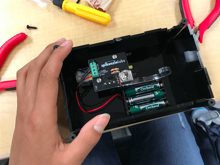
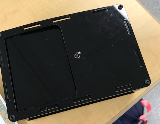
For my starter project, I chose to build the Useless Machine. When the user presses a switch, an arm pushes up a door to press the switch back to its original position. This project required me to develop my soldering skills, as well as improve my fine motor skills.
During this 2-day build, I encountered various challenges. In the first step, I accidentally soldered the switch at an angle to the PCB, instead of exactly 90° with respect to the PCB. I spent many minutes struggling to desolder the pins of the switch from the PCB. During this process, I tried 2 different methods of desoldering: the desoldering pump and the solder wick. While both tools were highly inefficient, the desoldering pump was easier for me to use, as I was able to remove more solder with it. After reviewing the steps of construction once again, I realized that this small discrepancy with the position of the switch would not affect its function at the end of my build. In addition, I experienced some difficulties with soldering itself. Many times, instead of the solder attaching to the PCB, the solder would simply melt onto the pen. After a few unsuccessful trials, I realized that my method for soldering was incorrect. Alternatively, I used the pen to heat up the joint, and then placed the solder wire on the opposite side of the joint (this way the pen never touched the solder wire). This method eliminated the difficulties I was experiencing with soldering. Towards the end of the build, I realized the my motor spindle was at an angle, instead of the proper 12 o’clock position. Since moving the motor spindle with my hands could break the gears within the motor, I decided to run the motor to change the position of the motor spindle. I installed 3 AAA batteries into the battery holder, and touched the battery wires to those of the motors. Using this method, I was able to successfully change the motor spindle’s position to exactly its correct vertical position.
Furthermore, this project challenged my technical knowledge. I learned the names and uses of various tiny electrical components. The board that I did all my soldering on was called the PCB, or the printed circuit board. This component supported all the electrical components of my project through a set of conductive tracks. Built within this specific PCB was the necessary circuit for my project. On the PCB, I attached a set of screw terminals. The function of these terminals were electrical connectors, connecting the wires from the battery with those from the motor. Using screws, I secured the wires to provide a strong connection. In addition, to screw the frame onto my motor, I used a piece called a weld nut. Unlike a regular nut, this was a heavy-duty nut and was designed to be welded to another object.
In addition to these materials, I used a snap switch, regular switch, LED, AAA batteries, and nuts and bolts. During the assembly of my PCB, I soldered on the screw terminals, resistors, switch, and snap switch. The regular switch was the mechanism that the user interacted with. It was connected in a circuit to a set of 2 resistors, which reduced the current flowing through the circuit. This prevented the LED from receiving an overload of current and possibly exploding. The snap switch was designed as a safety mechanism for the arm, preventing the arm from turning too far back and interfering with the PCB. When the back of the arm hit the snap switch, the circuit would be opened, stopping the motor from rotating further. All these electrical components were connected to the screw terminals, which function was described in the above paragraph. Apart from the PCB assembly, I also used a motor and a set of 3 AAA batteries. While the batteries provided power for the entire mechanism, the motor provided the rotational motion for the arm. Both the motor and batteries were connected to the circuit through the screw terminals.
