Reflection
“Goodbye BlueStamp” and “What’s Next?”
As I step away from BlueStamp Engineering, I think it is important to recognize the growth in my perception of engineering, myself, and my project. The first time I walked through BlueStamp’s doors, I entered with a basic coding background in Python, and minimal soldering experience. Yet, by the end of my first week, skills that I once had viewed as one of my weaknesses quickly became necessities that I used everyday. As I continued to use these techniques, whether it be for coding on my Arduino Uno and translating that code onto an Adafruit Flora, or soldering my final circuit together, the experience I gained at BlueStamp is one that will remain with me. While this project had its pitfalls (circuit shorts, memory capacity issues, and code errors), I think it was these conflicts that led to my deeper understanding of the term “engineering.”
When I first came to BlueStamp, I had envisioned engineers as people who worked with code, wires, and solder to build modern technologies. While this may be true to some degree, I believe that engineering really refers to group collaboration. A fantastic example of this is my project. Even though I did not have a clear tutorial or example on how to build my final project, I was able to use articles and forums to help troubleshoot some of the issues my individual sensors faced. Without the online documentation that others had done in the past, I would not have been able to complete my YouShoe.
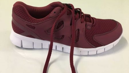
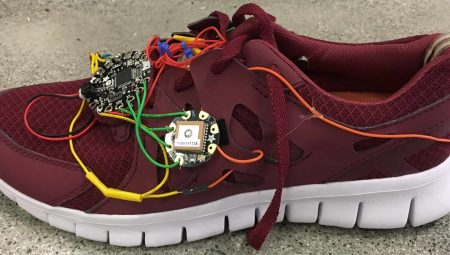
Lastly, I would like to speak towards my project. The YouShoe idea began with my passion for running. By combining technology with something that related towards my everyday life, I was able to see firsthand how engineering can have practical uses. This has inspired me to continue to work on my smart shoe project even after BlueStamp. For instance, in an attempt to make the project’s navigation system compatible with Google Maps, I plan to use the WiFi enabled Adafruit Huzzah ESP32 to connect to my phone and parse Google Maps data. This will provide more road-specific turn-by-turn directions. If this proves to work, I would want to print my project onto one consolidated PCB board so that it would essentially be a “chip” anyone could put into any shoe to create their own smart shoe.
Ultimately, my time at BlueStamp served to strengthen my interest in engineering. While I am still unsure as to what STEM-oriented major I would like to pursue in college, I have gained valuable experience into what the electrical and mechanical engineering fields may be like.
If you are interested in doing a similar project, my code, build of materials, and build plan are available at the buttons under “Final Milestone.”
Final Milestone
Refined Navigation Code/Interface, Circuit Soldered and Placed onto Shoe, Minor Bug Fixes
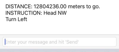
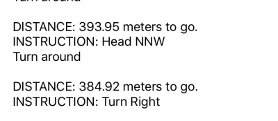
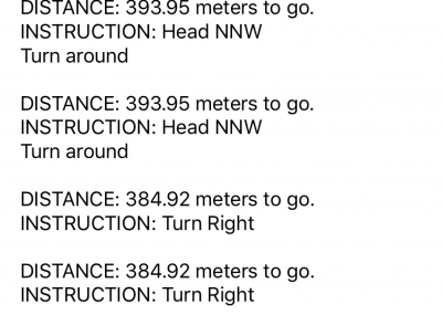
For my third and final milestone, I completed a variety of tasks to finish my smart shoe. I began by completely re-writing the navigation code. This included changing the code to give more accurate directions, such as adding options like “slight right” or “turn around.” I accomplished this by increasing the number of, and accuracy of if statements that were related to turn directions. In short, the way my turn-by-turn navigation system works is by creating an imaginary circle around the user. The circle is divided into a certain number of sectors that correspond to cardinal directions and directional degrees. Depending on what direction my courseTo() function decided upon, that direction will fall into one of the aforementioned sectors. Since each sector corresponds to a command (i.e ‘turn right’), by simply “adding” more sectors, I could increase the accuracy of the code’s direction. I also augmented the code to not only give vibration directions, but print the directions onto the serial port. The program will now update its data every five seconds and make a directional decision accordingly. I also had the program print how many meters the user was from their destination, so they would have a second way to check if they were heading in the right direction.
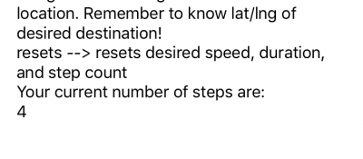
The next modification I pursued was the improvement of the pedometer function. I improved the weight threshold of the force resistor and added a 250 millisecond delay so that the function would not recount steps by mistake. I also added a “product info” function so that the user can see all of the possible functions of the shoe and how to use them.
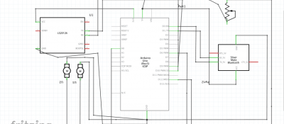
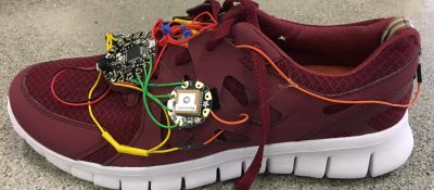
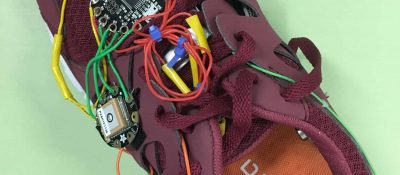
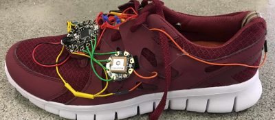
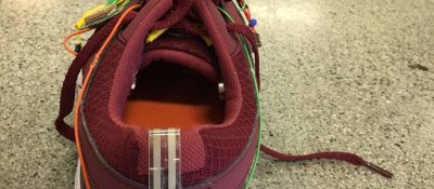
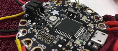
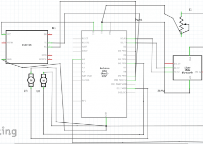
The last, most important change I completed was mounting my circuit onto the shoe. Until this point, I had been using alligator wires to connect all of my circuit together. Using my schematic, I arranged my circuit onto the shoe. I placed the Lipo battery under the laces using velcro, I then velcroed the Adafruit Flora to the Lipo battery. Next, I soldered all of my sensors to the Flora. I had originally intended to use conductive thread to put together my circuit but I quickly found that this thread was cheap and unreliable. Instead, I soldered all of the connections together, and placed electrical tape over important connections. I situated the force resistor under the heel of the shoe, motor disks on the insides of the shoe (just under the laces), GPS module on the left side of the shoe, and HC-10 module on the right. I finally was able to put together my circuit and have a functional smart shoe.
One of my biggest challenges during this last phase was getting the navigational code to work properly. I faced challenges with getting the program to decide upon a valid course and actually send turn directions to my iPhone Serial port. I eventually solved these errors by adding a series of delays and creating a new update function. The function was based on how far away from the desired location the user was, as opposed only to time. Another challenge I faced was getting my circuit on the shoe to function. Do to the large number of open-air circuits, I experienced a few shorts. I solved this problem by covering almost all connections with electrical tape and coiling up any additional wire segments. I also was unable to use the SD card reader in this project because the code and libraries I needed to have it function properly made my overall code file size too large to be uploaded to the Flora’s ROM (Read-only memory).
Useful Links:
Second Milestone
User Input, iPhone Compatibility, Various Settings, SD Card Reader, and Motor Disks Incorporated
For my second milestone, I added a variety of interesting features to my smart shoe device. To begin with, I added a navigation function to my code. Using some fantastic features of the Tiny GPS Plus library designed by Mikal Hart, I was able to integrate a turn-by-turn navigation system into my shoe. Users can identify direction commands by the vibrations of two tiny motor disks embedded in the shoe. The program works by first asking the user to input the longitude and latitude of their desired destination. Then, using a series of mathematic functions, the distance and course to the destination can be calculated. These functions send signals to my Serial Port where the directions are printed. Signals are also sent to the corresponding vibration motor over the GPIO 3 and 6 pins so that the user can be navigated without the use of a distracting cellphone. Most important among the functions from the library are the distanceToDestination () and courseToDestination (). The former function is primarily concerned with calculating how many meters remain in the course. The latter function is used to determine which turn direction to send to the user.
The next addition to the device is the implementation of user input. Currently, there are five inputs the user can choose from: pedometer, workout, navigation, GPS data, and reset. The pedometer is able to display how many steps the user has taken by reading data from a force sensor. The force sensor is actually a resistor that when pressed, alters the amount of continuous current flowing through it from the 3.3 volt pin. At the second pin of the resistor, current is split between a 1 M ohm resistor and the ground pin. Current that travels through the resistor will be decreased to that the Flora board is not overrun/damaged. The other path will take the current into the A11 pin so that the value of voltage can be read by the board and interpreted as a step.
The workout function, influenced by my love for running on Mt. Tamalpais, enables the user to input a desired speed and duration. These values are entered as strings and then converted to integers using the stringtoInt(). These integers are then compared to the GPS values for speed. The motor disks will then vibrate to indicate if the user is above or below their desired pace. The exercise program continues for the desired duration, using a simple timer function I created.
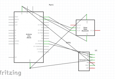
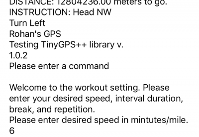
“GPS data” is now the command that allows users to see the Flora module’s data. Inputting this command will have the GPS print time, date, speed, longitude, and latitude as integers. “Reset” will reset the desired speed, duration, and pedometer to zero. All of this data can be sent and controlled wirelessly through a computer or iPhone. This is accomplished through the use of a HC-10 BLE module. The module is coupled to the main controller board using the RX/TX hardware serial ports. I used the Serial Bluetooth app (available on the Apple App Store) to control my device. In the next week, I hope to attach an SD card module to my setup so data can be collected even when a smart phone is not present. I also hope to improve the reliability of the GPS module and its data transmission. Lastly, I must mount all of the devices onto my shoe.
One of my biggest challenges throughout this project has been with my external modules added to my circuit. A good example of this has been with my bluetooth modules. Originally, I was using an HC-05 module to transmit gps data. However, I quickly found that this module did not work on my iPhone. Further research revealed that iPhones could not support the Light Bluetooth that the HC-05 transmitted. Furthermore, the HC-05 module was very unstable. Often, it would reconnect and disconnect from its connection with my laptop. Other times it would not send data. Luckily, I found a spare HC-10 module lying around. This transmitted BLE bluetooth, the only form of bluetooth that iPhones could support. After attaching this module however, data still did not transmit. I later found out some additional code I needed to add to support the BLE module. Finally, I had a reliable connection between my phone and the smart shoe.
First Milestone
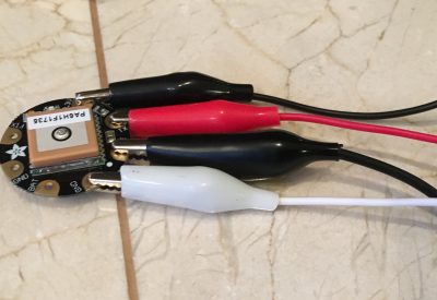
GPS Module and Bluetooth Configured on Adafruit Flora
Starter Project
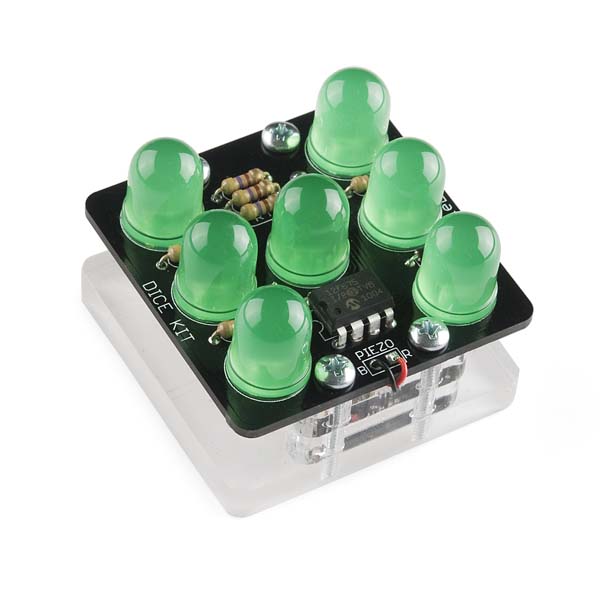
Electronic Dice Kit
Image Credits: From Bottom To Top
http://www.spikenzielabs.com/SpikenzieLabs/dicekit_files/dkschem2.png
https://upload.on-running.com/spree/products/83/listing/cloud_black_white_listing.png?1513780809


