Reflection
The six-week program went by in an instant. I did a Blue Stamp project last year so I was familiar with how the Blue Stamp process goes and came into this program with a good amount of programming and overall engineering skills. I came into the program eager to refine and further my engineering skills. I would not have traded this experience and the skills I have learned for anything, not even for a couple extra hours of sleep. After intense engineering, I now have a working robotic hand and a refined skill set ranging from understanding the meaning of flex sensors, rotary encoders, and stepper motors, to new strategies to debug and to get past difficult problems. Something that I learned at my time in Blue Stamp that impacted my future in engineering is the idea of attention to details. In the last three days before the showcase night, I was confirming that my project was working and while I was doing so, I burnt out two of the servo motors. This happened because I incorrectly plugged in my battery as well as the two motors, leading to the motors overheating and breaking. This error could have easily been prevented if I paid attention to the small details of my project. I ended up borrowing the two servos from a friend who had extras. I learned that I have to understand every component, every circuit, every part of my project and how they affect the thing that I am working on. Even if it is as minor as miss reading a schematic, it is very imported to understand how the various components could be affected if a problem occurs. I will take this learning experience both to future projects as well as in all other aspects of my life.
After Blue Stamp, I still want to be an engineer and work in the field of computer science, and I am most interested in biomedical engineering as well as software engineering. I enjoyed working with the robotic hand as it sprouted an interest in biomedical engineering where I could possibly create projects to help improve the health of individuals.
Here is my final GitHub repository. GitHub Repository (https://github.com/robertciulla/3D-Printed-Robotic-Hand)
Modification
For my modification of the 3d printed robotic hand, I created wrist motion to accompany the finger movements. I wanted to do this modification because I felt that just having finger movement felt very limited and I wanted to make the hand look more realistic. I used a rotary encoder, easy driver, and a servo motor as my main components for the wrist. I originally wanted to use a stepper motor because of its increased strength and durability compared to a servo, but while assembling it, I came across various problems. I checked my wiring many times as well as the effectivity of the driver. Over a day of debugging, I was able to locate that the problem was that the potentiometer on the driver was turned to a resistance in which the stepper motor could not function on. After researching the correct resistance level, the stepper motor worked consistently with the program. I was already working with servo motor designs when I figured out the stepper motor problem, so I thought that it would be easier to continue using the servo. I proceeded to attach the servo to the bottom cuff of the robotic hand with some metal scraps in order to keep it in place. I used a manual rotary encoder to turn the servo. A rotary encoder is a variable resistor much like the flex sensors that I used in my main project. The rotary encoder is built with a small disc inside of it with evenly spaced common pins around the edge. The common pins are small slits of conductive metal that read when two output pins are passed over. When the common pins move with the disc, the output pins make contact with the common pin in evenly spaced intervals. These contact points are based on the rotational spin of the disc. If the difference the two contact points of the two pins are long, then it means the encoder is spinning at a slower rate, if the distance measured between the contact points is shorter, then the encoder is moving faster. The Arduino then reads the values produced by the encoder and based off of the certain value, it tells the servo to turn to a certain degree. This rotation correlates to the rotation of the wrist.
Base Rotation

Second Milestone
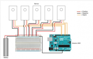
In my second milestone for the robotic hand, I attached my servos into the 3d printed chamber. I also strung the corresponding tendons through the fingers and made some small touch ups on my glove and flex sensors. Prior to this milestone, I had my flex sensors tapped onto the glove. Due to the fact that electrical tape is very unstable, I decided to sew on the flex sensors as well as sew the PCB board onto my glove that contains the flex sensor connections. I also refined my circuits so they used fewer wires, helping the organization of my project. For the attachment of the tendons, I strung wires up and down each of the fingers and secured them to the end of each of the servos. When the servos rotate, the ends of the servo bits pull on the strings, moving the fingers up and down. I used flex sensors to control the movement of the servos. Since the flex sensors act as voltage regulators, the increase in resistance when the flex sensors are bent, sends a specific value to the Arduino. The Arduino then reads the value based on a set of commands that map the resistance of the sensor. The Arduino reads the values of the flex sensor through the analog pins on the board, transferring the values into a range between 0 and 180 degrees. The program then tells the servo to rotate based on the value produced by the flex sensors. When the flex sensors are bent to a higher degree, the servos turn closer to 180. If there is minimal resistance applied to the flex sensors, the servos will move closer to 0 degrees.
Here is the code that I used to get my servos and flex sensors running.
Throughout my second milestone, I ran into some problems regarding my tendons (blue wires). I originally used sewing thread instead of wire, but it was an extremely tedious process to push them through the hand as well as attach them to the servos. This process set me back a couple days until I switched to use wire, which is more sturdy material. I felt comfortable working with the flex sensors and servo code as well as the schematic, as modifying the code based on the resistance did not pose any problems.
First milestone
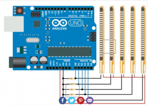
In my first milestone for the robotic hand, I connected the five flex sensors as well as five servos to the Arduino. The flex sensors act as a resistor that can be manually changed by its shape. When bent, the resistance in the flex sensor increases. When it is completely flat or barely bent, there is very little resistance. This resistance given by the flex sensors is then mapped by a certain value between 400 to 700. This value is then translated through the “map” function in the code. This function translates the value between 400-700 to a value between 0-180 degrees. 0-180 is the optimal working conditions for the servos in the robotic hand. If the value from the flex sensor is around 400, the value given to the servos will be closer to 0 degrees, whereas if the value given from the flex sensor is closer to 700, the servo will move closer to 180 degrees. When the servo gets this number, the motor will turn the specific amount. The rotation of the servos will dictate the future movement of the fingers. The bend of the flex sensors will be dictated by one’s hand in the glove.
Flex sensor schematic

Servo Schematic

Starter Project
My Starter Project is the light organ. The light organ is controlled by sound, influencing the pattern in which the LED’s blink. The microphone receives sound waves from an outside source which are read by the larger IC chip (HCF4017). The IC chip is a pre-programmed circuit that receives a sound from the microphone as a set of numbers. These numbers are read and distributed at an extremely fast rate straight to the smaller IC chip (NE555P). The smaller IC chip sends out an accurate time delay, one that could be read more easily by a human. The visual display of the LED’s depend on the sound present, the sharper the sound, the faster the LED’s will blink. There are 11 resistors present, functioning by regulating the electrical current. There are seven transistors, acting as on and off switches for the circuit. There are four capacitors that store an electrical charge for later use in the circuit, and two potentiometers are manually controlled to influence the flow of energy. This project was not too difficult to assemble and understand, but I did come across problems when putting the LED’s in as well as some transistors. I learned that although the transistors look the same, they could still vary in type. I also learned the specific function of both IC chip and how they relate to each other.
Credit


