Reflection
This project was a step for me to decide if engineering is a path I would like to pursue in college and future endeavors. Although I struggled with many of the components, I would like to learn more about mechanical and electrical engineering. Both of these fields compliment each other and by creating a project involving design and circuitry, I exposed myself to a different side of engineering in contrast to my computer science background. In terms of future engineering projects, I am interested in creating projects with a more construction-based design and expanding my knowledge of mechanical engineering, but learning about circuitry and the libraries for each sensor was fun and challenging. This project pushed me to the limits of my patience, but I am proud of the final product and would love to approach shoe companies with my prototype as this could become a huge product with the proper modifications and guidance.
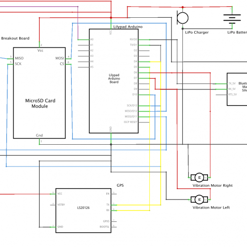
All my code, documentation, and planning is available on my GitHub, Build of Materials, and Schematics.
My presentation video is available below!
Final Milestone
Final Milestone Images
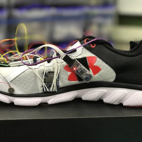
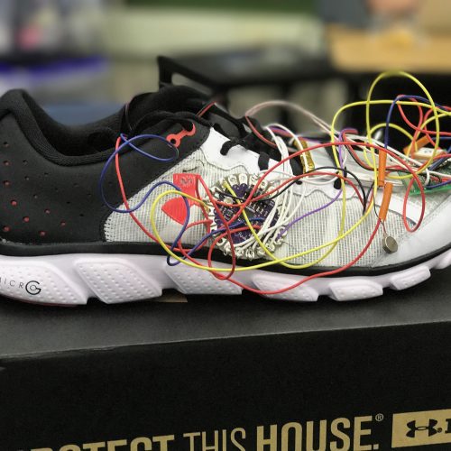
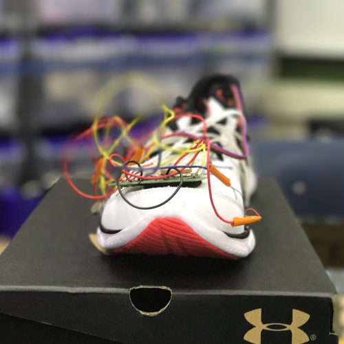
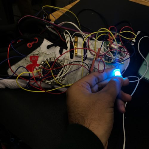
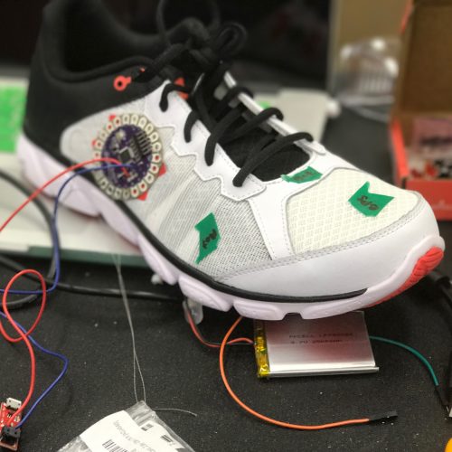
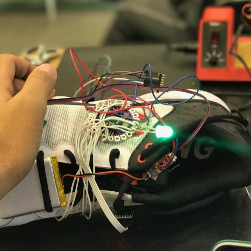
My final milestone added a few modifications to the shoe and changed the whole user experience using prompts and easy commands. I added a help command as well, so the user does not have to memorize all the commands. I had a few challenges with the coding which will be explained in detail below.
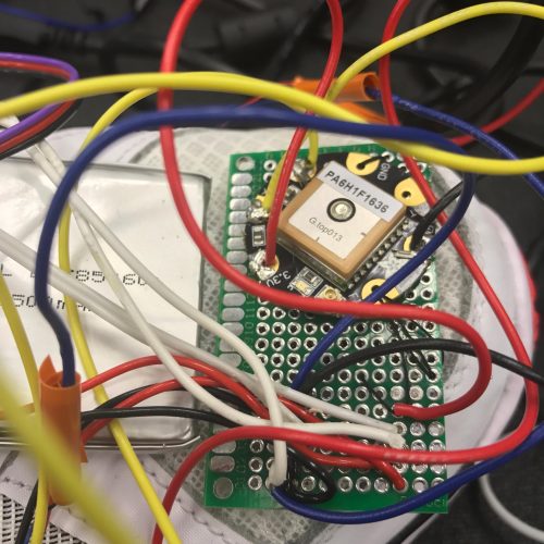
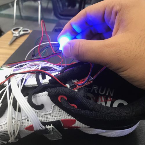
First, I worked with the PCB board. Rather than trying to excessively attach power and ground wires to the + and – pins on the Lilypad, I decided to just connect two wires (connected to PCB) to the Lilypad. From there, the components and sensors are all connected to the PCB board for voltage and ground. Although this made the shoe look more crowded, the connections and reliability increased indefinitely. I connected this to the shoe by using velcro.
Another component added is a personal favorite: the Adafruit GPS module. At such a cheap price, this module can do anything from tracking speed, determining user direction, distance to a destination, and the date at a certain location. Using this feature allows the user to learn about the time and direction to a certain location. I was fortunate to find some code online to help me jumpstart the coding process. I used TinyGPS++. I was able to play around with the GPS which was a lot of fun. I decided to take the challenge of adding a navigation feature which is actually one of the coolest features of my shoe. The GPS is attached to the PCB board by using thread. I have two vibration motors, one on each side of the shoe. The motor on the right will vibrate if the GPS determines that you need to turn right to reach the destination and left for turning left. This feature allows users to be able to navigate with having their phone on them which is something that runners would use because phones easily distract people.
I learned a little about each component. I found out that the GPS module does not receive anything from the Lilypad; it simply transfers data to the Lilypad. Therefore, the RX pin on the GPS module does not have to be attached, as it functions without it. I also learned about the compatibility of the GPS with the pulse sensor. This was a challenge to figure out because the pulse sensor is constantly running to scan the user’s heart rate, so I had to create an if statement to force the pulse sensor to stop while the GPS module is scanning location. This was vital as the GPS needs to be the only module transmitting data. This was the hardest challenge that took a few days, but being able to overcome the obstacle was extremely rewarding. Another challenge I faced was coding in general. I had to use the GPS methods already existent to navigate the user to the destination desired.
I worked a lot on the code, so please feel free to view it on my Github. The materials I used are available on my Build of Materials.
Second Milestone
Second Milestone Images
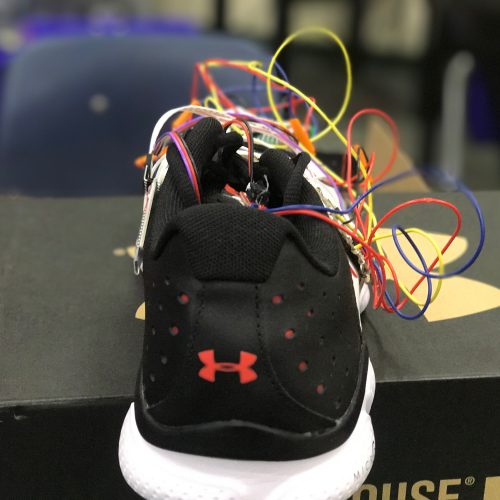
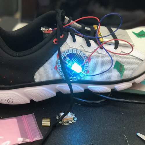
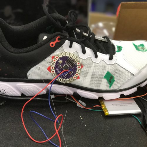
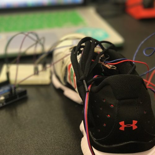
My second milestone consists of hardware modifications, as I sewed the components onto my shoe. This prototype is what I expected to have completed by the end of the BlueStamp program, so I will be adding modifications (including GPS) to ameliorate the device.
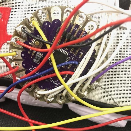
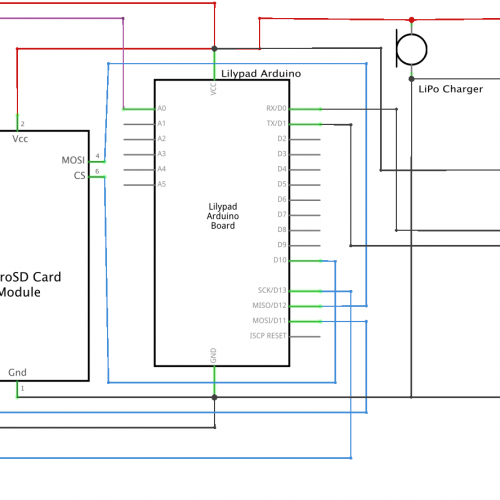
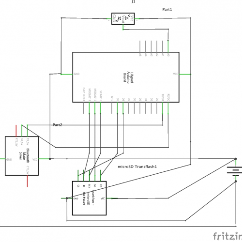
One component that I changed was the SD card reader. I decided to purchase a MicroSD card breakout board+ from Adafruit to replace the reader I had from Sparkfun. The reason for this change was due to the lack of reliability in the reader as it could not read the SD card very often. This new breakout board is much more reliable and has been implemented into the shoe. The only difference for me was that I changed some of the wire connections to the Lilypad. One new component I added is the Bluetooth module. I had first selected an HC-06, but due to the absence of BLE, or Bluetooth Low-Energy in the HC-06, I had to purchase a new bluetooth module that supports the connection between an arduino and my Iphone. Therefore, I purchased the HM-10 and this proved to be a good purchase. Delving into what the Bluetooth module does, it has four necessary pins: Vcc, ground, TX, and RX. This is very simple to connect and use as there is no need for additional code and most of the bluetooth aspects are handled internally. All I have to do is give it power and attach its RX to the Lilypad TX and its TX to the Lilypad RX. TX and RX stand for Transmit and Receive, respectively, which are essential for flashing code onto the Lilypad as well as handle bluetooth commands. I had trouble with the TX and RX pins because the Lilypad cannot handle both the Bluetooth module and computer accessing the same TX and RX route, but fortunately, there was another pin, and circuit, for RX and TX on the Lilypad which allowed me to connect to Bluetooth while updating the code. For permanence, I soldered wires onto the Lilypad, LiPo charger, and SD card breakout board. This proved to be challenging as many of the sensors connect to the power and ground pins on the Lilypad.
I decided to sew many of the components onto the shoe using conductive thread. Some of the wires I cut (for multifilament purposes) were connected to the Lilypad using the thread which was surprisingly reliable. Most of my accomplishments consist of me attaching components onto the shoe. I also used velcro to connect the bluetooth module and heart rate pulse sensor to the shoe because the pulse sensor may be in a different location depending on the user’s foot and the bluetooth module did not have any reliable holes for sewing and using velcro proved to be a reliable solution.
Most of my code remains the same as I only adapted the code for the change of pins for the SD card breakout board. The code is on my GitHub.
First Milestone
First Milestone Images
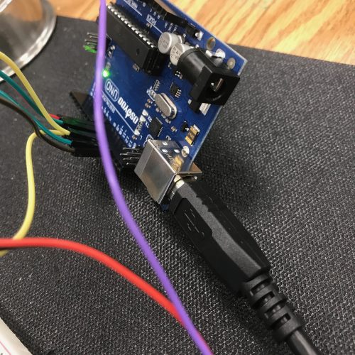
My intensive project is a SmartShoe that is able to track heart rate and location to store it into an SD card and communicate with a Bluetooth-enabled cell phone device to give data. The goal of this product is to ease runners who do not want to carry their phones as they run but still want data regarding speed and heart rate. The project was inspired by Nike’s new smart shoe and I decided to add features that would normally be on the wrist, rather than the foot. Since nearly everyone in the world wears shoes on a daily basis, having a smart shoe would be accustomed to nearly everyone and eliminate the need for an extra accessory, such as a smart watch. My first milestone is a prototype of this project. I used an Arduino UNO, pulse sensor, and microSD card to transfer the heart rate data from the pulse sensor to the SD Card. I used the Arduino IDE to code this transfer which proved to be a challenge once I started.
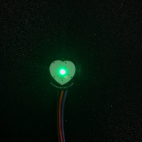
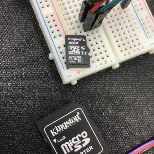
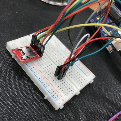
I first worked with an SD card writer and a pulse sensor monitor individually and thanks to Sparkfun, I was fortunate enough to find sample code to work off of (the SD card code and Pulse sensor code). I was able to get both of these components to work, but faced the challenge of coding to make both them work together. In addition, the Arduino Uno proved to be more useful for prototyping as there is no soldering required whereas my final project would utilize the Arduino Lilypad. The pulse sensor has three jumper cables: red, black, and purple. The red jumper is the input for power, the black is for ground, and the purple is to output the heart rate data to the Arduino. I connected the purple to A0 as that was indicative in my code. The SD card has 6 pins: ground, power, CS, D1, SCK, and DO next to the SD card reader. The ground pin is connected to the ground header on the Arduino UNO and the VCC to the 5V header on the UNO, and the rest of the pins are for the SPI (Serial Peripheral Interface). The microcontroller on the Arduino UNO would be the “master” and the SD card is the “slave” which allows the microcontroller to control when data is sent from the Arduino to the SD card writer. The master generates the clock signal and the clock keeps both sides in sync by telling the receiver when to read the next bit of data received, but the data transfer can go both ways. There is a MISO (Master in, Slave out) and MOSI (Master out, Slave in) to indicate which way the transfer of data is going.
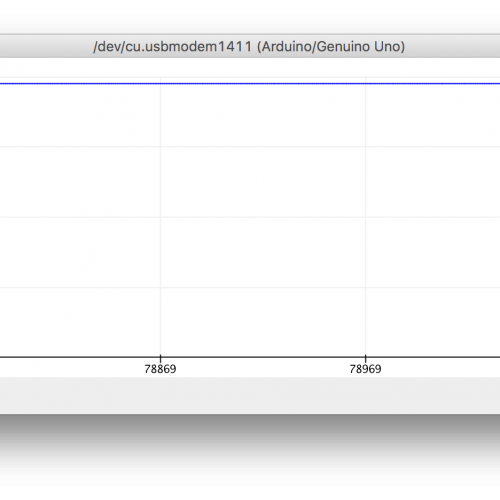
I started the project by using the pulse sensor. I was able to use the serial monitor and plotter to collect data regarding the heart rate of the user and the plotter uses a graph to show the data. The code I used for the SD card at first was taking the input from the Serial Monitor and putting into a demo file in the SD card. I understood the code and modified it to make sure that the data from the pulse sensor went directly to the SD card, rather than waiting for user approval in the Serial Monitor. For more information regarding my code, please refer to my GitHub.
Starter Project
Starter Project Images
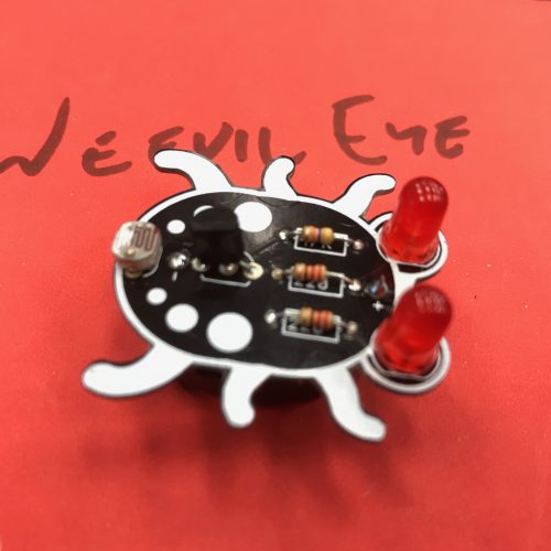
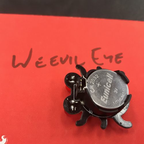
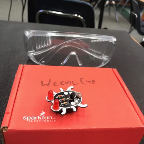
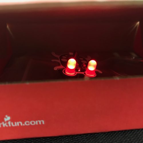
My Starter Project is the WeevilEye from SparkFun which allowed me to enhance my soldering skills and learn about the functions of the basic components of a circuit. I also learned about how circuitry works and important terms describing it.
The battery clip with the Eunicell 3V Lithium Battery is the power source for the entire circuit. First, the energy flows from the battery to the photocell which is also known as Cadmium-Sulfide cells or Light-dependent resistors. This component is a resistor that restricts the amount of electrons that pass through the component depending on the amount of light present. The more light, the more energy passes through the resistor. The next component is a transistor, or to be more precise, the unijunction transistor. The UJT emits a very small current if there is no voltage present between the emitter and either of the base leads and if there is a large voltage, the component combines the two base lead currents to create a larger current, but the smaller base lead only contributes a very small current to the larger voltage. Next are the resistors; this project used two 220 ohm and one 47k ohm resistors. These resistors restrict how many electrons pass through them to avoid overheating the LEDs. The resistor is a passive device but it provides resistance to the current flow by acting as a gatekeeper controlling the amount of electrons. The last component of my project is the LED, which stands for Light-Emitting Diode. This is a semiconductor that emits visible light as an electric current passes through it, and the intensity is dependent on the current strength. This is why the LEDs light up when the photocell allows energy to pass through in the darkness. An LED consists of P-type semiconductors and N-type semiconductors that form a P-N junction that allows visible light to pass through.
The LED is a diode, so it is polar with a cathode (positive) and anode (negative), as the electrons are transferred from the cathode to the anode. The transistor and battery clip are polar as well; therefore, their orientation in the circuit is important.
Regarding circuitry, I learned about resistance (ohms), voltage (volts), and current (amps). Voltage is the electromotive force for electrons, whereas the current is the flow of electrons. The resistance is what controls how many electrons pass through to avoid overheating in a project. These three components are tied together by Ohm’s law, I=V/R. Therefore, as voltage increases, there is a stronger current and as the resistance increases, there is a weaker current.


