
Phone Controlled Robot Arm
Engineer
Rishab K
Area of Interest
Industrial engineering/MIS
School
Homestead High School
Grade
Incoming Senior
Third Milestone


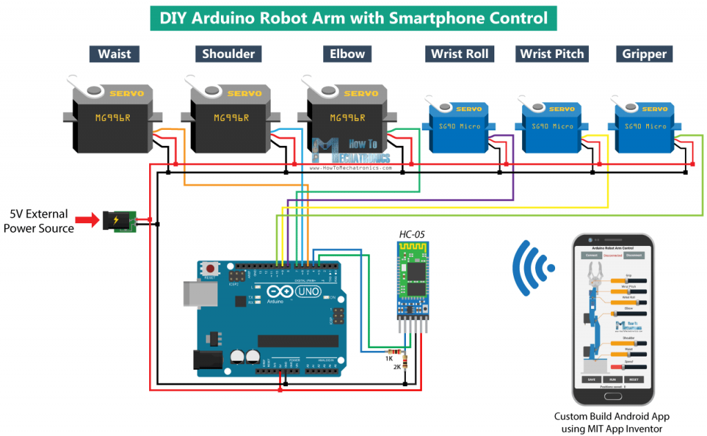
For my third milestone of my phone controlled robot my goal was to create and program a phone application with sliders that could relay data to the Bluetooth module that the Arduino could use to set the servos at a certain position. When it came to creating the phone app I used MIT App Inventor which simplified the whole process since it is block programming and drag and drop formatting when building the frontend of the app. The next part of the milestone was hooking up the Bluetooth module. This process was made easier when I found the schematic below. The next part was to program the Arduino to receive the data from the Bluetooth module and convert the data so it could be used in my program to move the servos. I was able to get the data by using the Serial.read() function which reads and returns the first byte of incoming serial data available and the map() function to scale my data to a number my servo could use. My final part was of organizing the wiring to make it easier to see where wires are going and also making my project more visually appealing.
One of the issues I ran into during this milestone was sending the data from the phone to the Arduino by using the HC-06 Bluetooth modules as a middle man. Initially, I tried to send the data as a 2-byte integer but I was running into a problem when trying to read in the data to the Arduino. The way I solved this problem was changing the code in my app to send each integer as a char then converting the data from a char to an int which I could use in my code. Another thing I had to keep in mind was something I figured out during the second milestone which was that the 2 servos control the height and the reach of the arm could interfere with each other when they were at certain positions. The quick workaround I was able to create was limiting the servos movement so they would never be in a position where another servo could not move. The most insignificant problem I ran into was when I tried to work on the cable management of my robot arm, I actually limited the range of motion of my arm forcing me to find the right balance of functionality and being organized.
Something I learned while working on the third milestone was that the HC-06 Bluetooth module needs resistors to protect the Bluetooth module from any possible damages. Another interesting thing I found was that when I was trying to get the data sent from my phone to the Arduino the data was originally getting converted to the ASCII value of the number and by casting the number to a char I was able to get the integer value I was looking for.
My next steps after this program are to try and continue to add modifications such as an ultrasonic sensor that can detect objects in front of the arm and also working on new projects such as the car chassis that I got from the main build kit.

#include <Servo.h>
#include <SoftwareSerial.h>
Servo myservo1, myservo2, myservo3, myservo4;
int pos = 0;
int bluetoothTx = 2;
int bluetoothRx = 3;
SoftwareSerial bluetooth (bluetoothTx, bluetoothRx);
void setup() {
// Maps the servos to there respective PWM pins
myservo1.attach(5);
myservo2.attach(6);
myservo3.attach(9);
myservo4.attach(12);
// Moves all the servos to starting positions
myservo1.write(90);
myservo2.write(160);
myservo3.write(72);
myservo4.write(0);
//Setup Bluetooth serial connection to computer
Serial.begin(9600);
//Setup Bluetooth serial connection to andriod device
bluetooth.begin(9600);
}
void loop() {
//Reads from bluetooth and writes to the usb serial
if(bluetooth.available() >= 4){
unsigned char digit1 = (uint8_t)bluetooth.read();
unsigned char digit2 = (uint8_t)bluetooth.read();
unsigned char digit3 = (uint8_t)bluetooth.read();
unsigned char digit4 = (uint8_t)bluetooth.read();
Serial.println((char)digit1);
Serial.println((char)digit2);
Serial.println((char)digit3);
Serial.println((char)digit4);
String realNum = “”;
realNum.concat((char)digit1);
realNum.concat((char)digit2);
realNum.concat((char)digit3);
realNum.concat((char)digit4);
unsigned int realservo = realNum.toInt();
Serial.println(realservo);
if (realservo >= 1050 && realservo < 1140){
int servo1 = realservo;
servo1 = map(servo1, 1050, 1140, 50, 140);
myservo1.write(servo1);
Serial.println(“Servo 1 is ON :”);
delay(10);
}
if (realservo >= 2000 && realservo < 2160){
int servo2 = realservo;
servo2 = map(servo2, 2000, 2160, 0, 160);
myservo2.write(servo2);
Serial.println(“Servo 2 is ON”);
delay(10);
}
if (realservo >= 3072 && realservo < 3180){
int servo3 = realservo;
servo3 = map(servo3, 3072, 3180, 72, 180);
myservo3.write(servo3);
Serial.println(“Servo 3 is ON”);
delay(10);
}
if (realservo >= 4000 && realservo < 4180){
int servo4 = realservo;
servo4 = map(servo4, 4000, 4180, 0, 180);
myservo4.write(servo4);
Serial.println(“Servo 4 is ON:”);
delay(10);
}
}
}
Second Milestone
For my second milestone, my goal was to wire all the servos up to the Arduino and get them to run by writing some code that talks to the servos and tells them what position to be in. When it came to wiring the Arduino I decided to use jumper cables for my wiring because they were stronger than the normal wires I tried to use which kept snapping off. Then once the wires were all secure I did some testing of the servos, setting them to different angles until they could not move further and then wrote down the range. By finding the range of motion where the servos could freely move I was able to make sure the servos would not try to force a position which could lead to the eventual overheating of a servo.
Some of the problems I ran into while trying to complete the wiring for the second milestone was that 2 of my servos were not running and was causing my circuit to short. After looking into the issue more I found out that the circuit shorting could be caused by too little resistance being applied or a wiring mistake. I knew that the more likely cause for the circuit shorting was a wiring issue because I knew that each servo had a resistor to regulate the current going into the servo. When I checked the wiring I found that for the 2 servos that were not working, the ground and power cables were flipped and after flipping them all the servos were able to run. Another problem I ran into was that when the servo that controlled the reach of the arm was beyond a certain degree the servo that controlled the height could not move freely and vice versa. I was able to fix the problem by limiting the range of motion of the servo that controls the reach of the arm. The last problem I had to debug was that my servos were getting stuck when they were trying to move. I was able to figure out that some of the screws were too tight and I needed to loosen them to get the servos full range of motion.
Something that I learned from the build process was that an Arduino is controlled by an electrical pulse of variable width or Pulse-Width Modulation (PWM). When the PWM pulse is sent to a servo the pulse determines the position of the shaft, and based on the duration of the pulse sent via the control wire the rotor of the servo will be turned to the desired position. There are 3 main PWM pulses: the maximums which turns the servo to 180, minimum which turns the servo to 0, and neutral which turns the servo to 90. When using PWM with an Arduino, the Arduino simulates analog signals by quickly switching on and turning off the voltage that is sent to each servo. By using this technique the Arduino has a stronger control of the power that each servo receives. My next steps are to finish the android app using MIT App Inventor that controls the servos, organize the wiring, and start on modifications.


First Milestone

My first milestone for the project was to construct the robot arm. To construct the Arm I found a guide that gave step by step instructions that were clear and easy to build the arm in half a day. While constructing the robot arm I started to test the servos before installing them to ensure that the servos were in the right position since servos turn 180 degrees so if you install them upside down you may have to disassemble most of the arm which I did not want to do.
The only 2 problems I ran into during my first milestone was receiving the parts a little later than I expected and some of my servos overheating. I was able to solve the servo overheating problem by using resistors to lower the amount of current going into the servo. After I got the parts I got them it was smooth sailing from there because I was able to find a video on how to assemble the arm.
Some of the things I learned while constructing the arm was the use for each servo on the robot arm. The servo mounted on the bottom of the robot arm controls the rotation of the body of the arm and allows the arm to pivot 180 degrees around the base. The servo mounted on the top of the arm controls the opening and closing of the arm allowing it to open and form a 180-degree angle and close to form a 0-degree angle. The servo mounted on the right side of the arm controls the height of the arm. The servo mounted on the left side of the arm controls the reach of the arm.
