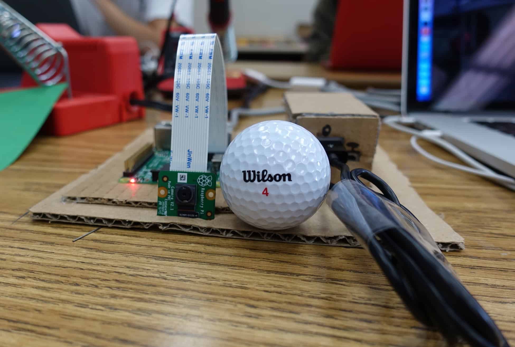
Hi, my name is Rin and I am a rising sophomore at Lynbrook High School with an interest in Computer Science. At BlueStamp, for my starter project, I chose to make the Mini POV and for my intensive project, I chose to use computer vision to track a golf ball, with inspiration coming from my grandma, who often finds it hard to keep track of the golf ball when she plays golf. To know what materials to use, I referenced this website, and I used a Raspberry Pi 2, a Raspberry Pi Camera Module, and a Li-ion battery.
Final Milestone
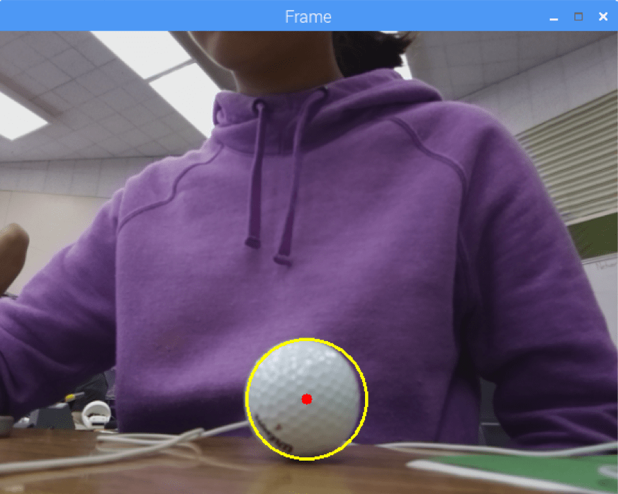
For my final milestone, I implemented a more robust algorithm to detect the golf ball and upgraded my cardboard prototype so the battery would have a fixed location.
Another feature of the golf ball that from whatever angle you view the golf ball, the edges look like a circle, so I tried implementing an algorithm that would use both the HSV filtering and some circle detection to determine where the golf ball was in the frame. In this case, I used the hough circle function from the openCV library.
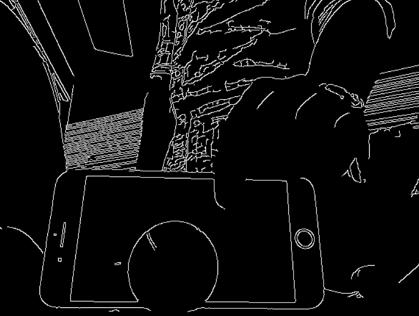
In the code, after I check that there’s at least one contour (a white area after the HSV filtering), I change the original frame to grayscale from BGR (blue, green, red), and I try to find the edges in the frame using the openCV canny function. After I find the edges, I originally immediately passed that the image to the hough circle function (, which detects circles in an image), but it couldn’t detect golf ball, even if the edge the golf ball clearly looked like a circle.
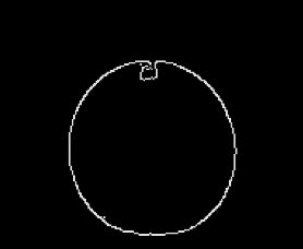
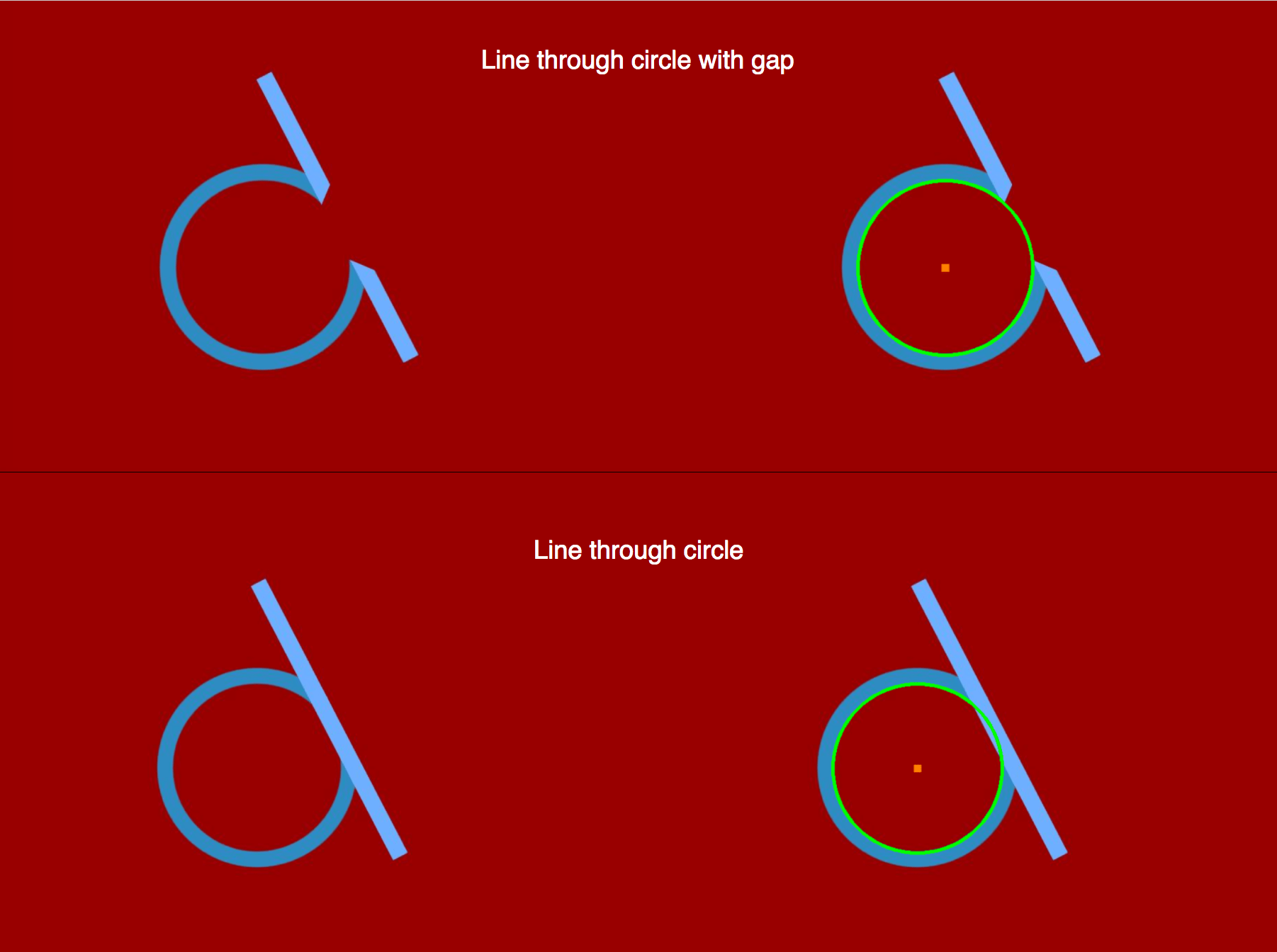
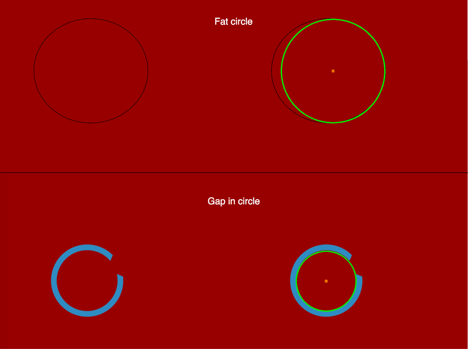
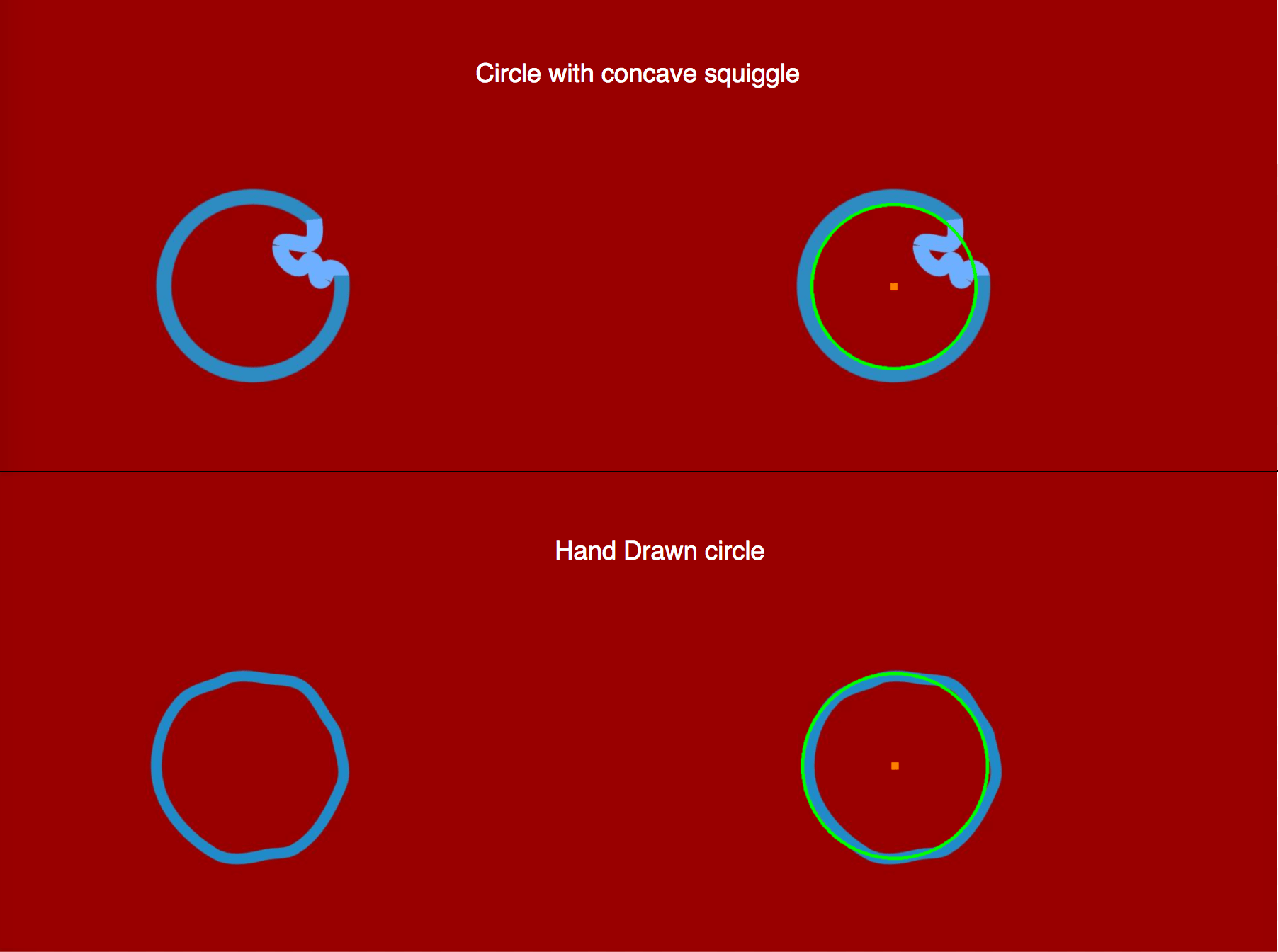
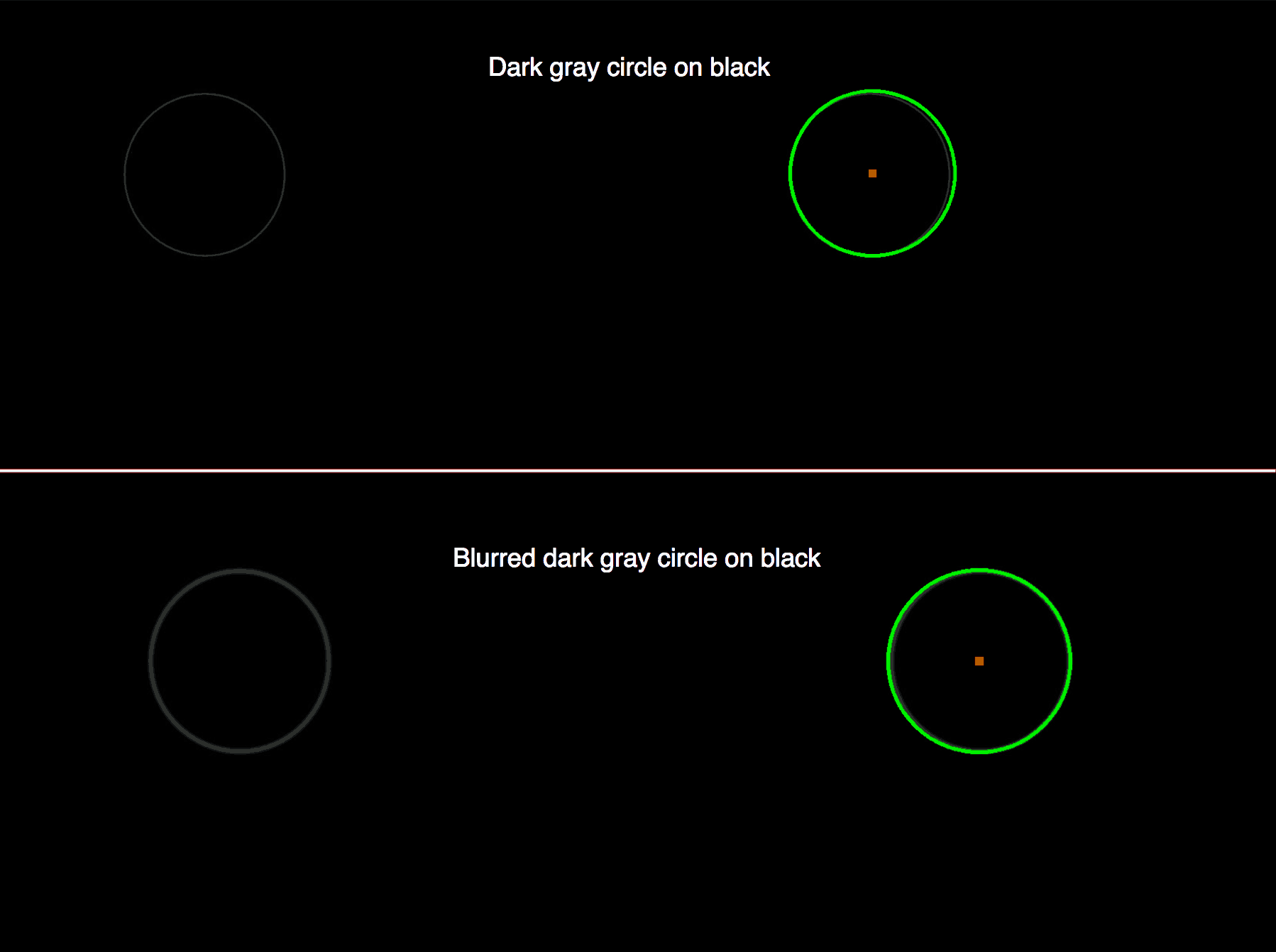
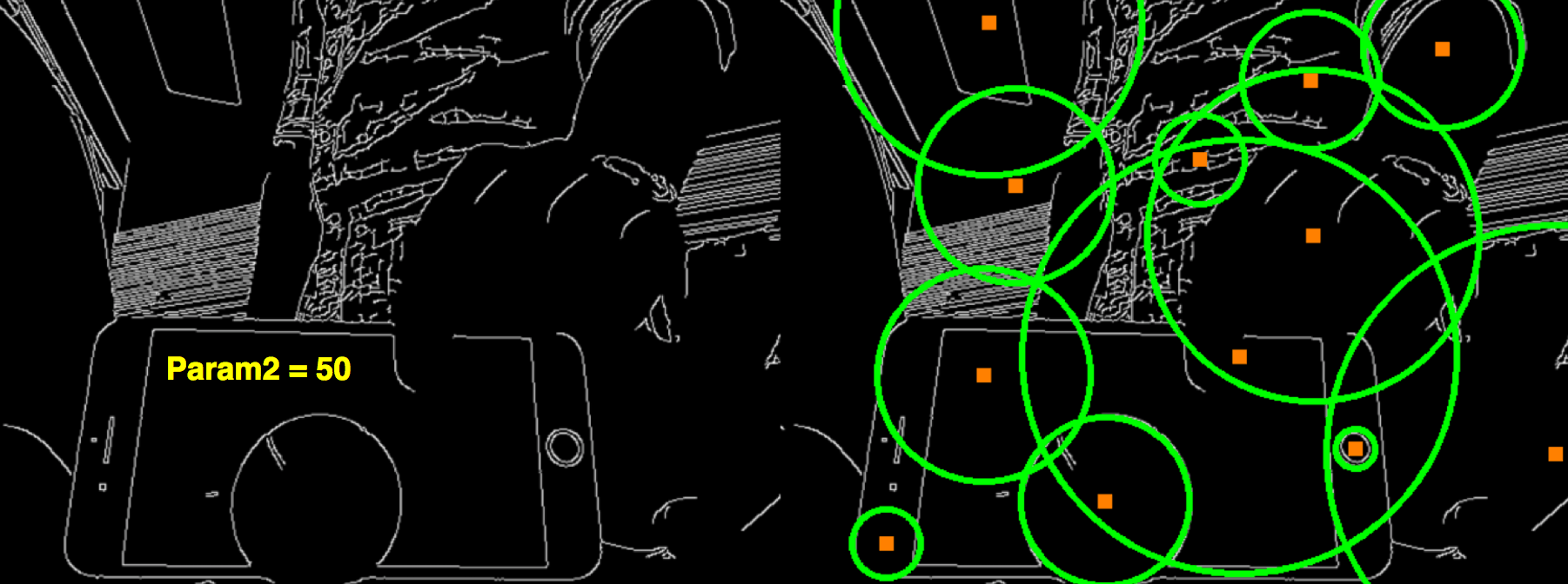
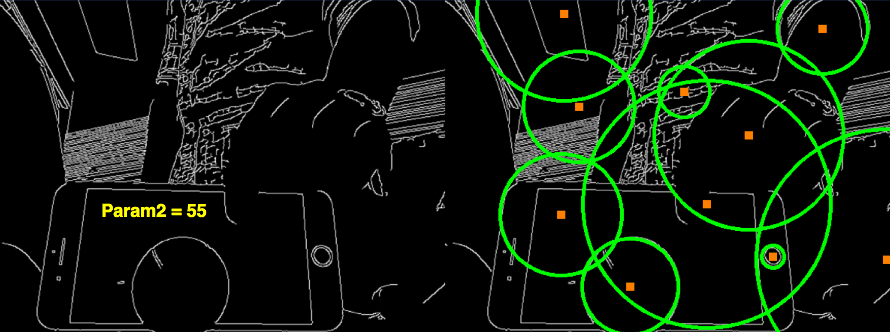
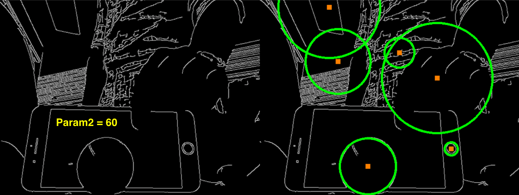
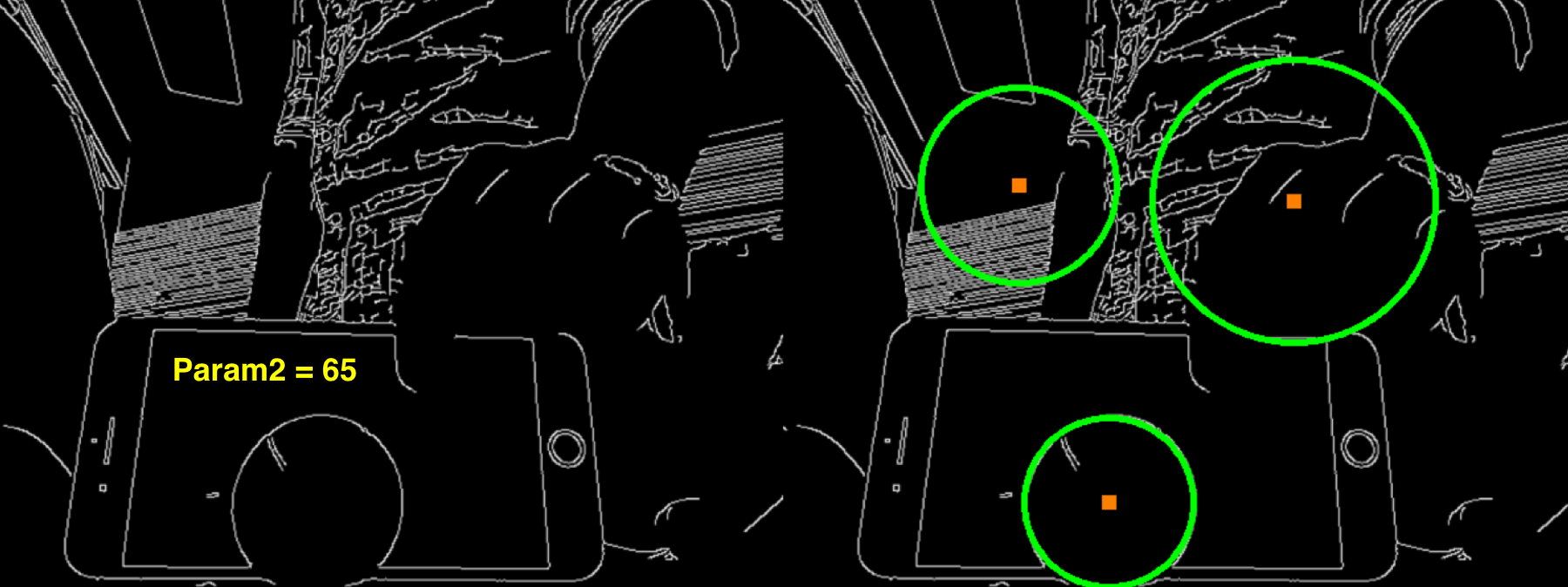
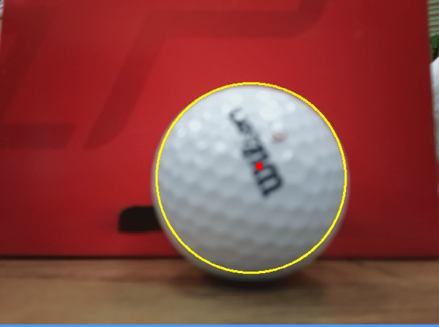
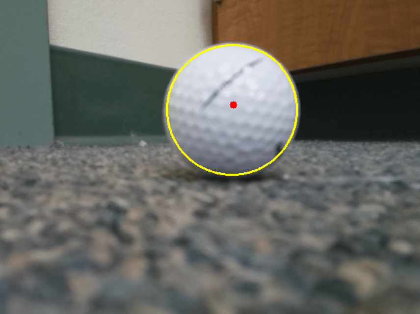
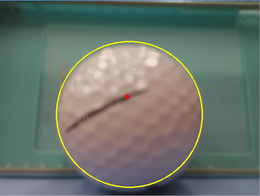
After that, I passed several pictures of imperfect circles to the hough circle function, shown below:
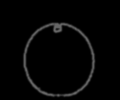
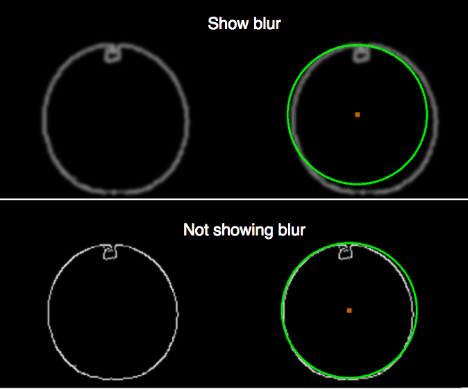
After all those tests, I thought that it wasn’t detecting the circle because the edge was quite jagged even on a minimal level. So then I tried a circle that was slightly blurred, passed that to the hough circle function, and it detected the circle. Then I tried applying a Gaussian blur (which blurs the edges and reduces noise) to a screenshot of the golf ball’s edge multiple times, after applying it 9 times, it was finally able to detect the ball.
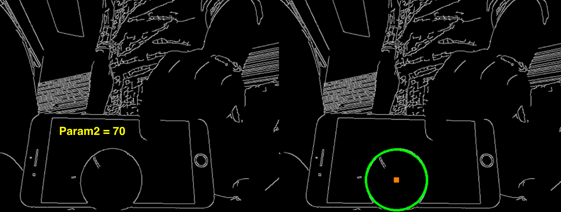
Then I tested a screenshot of an entire frame, and I added two parameters to the hough circle function, param1=70 (higher threshold passed to canny), and param2=50 (accumulator threshold for circle centers during detection). When I ran that test, I saw that too many false circles were being detected as well. I read on stack overflow that if param2 is too low, then the function will detect false circles, and it it’s too high, then it won’t detect the circles you want it to. So then I tried incrementing param2 by 5, and it detected less and less false circles. Finally, when param2=70, it only detected the golf ball.
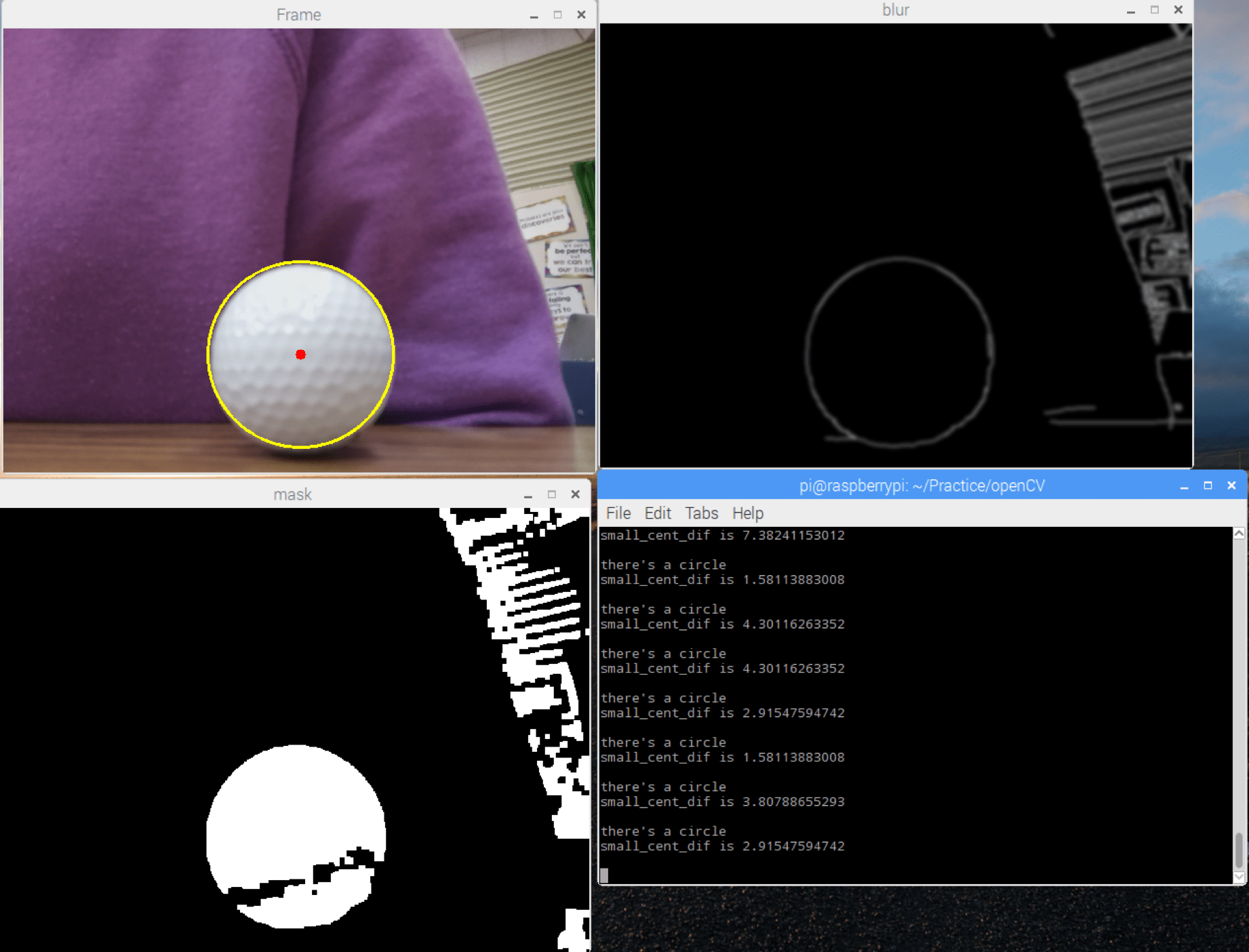
I tried detecting circles in real time, and it was able to detect the golf ball! Then I tested algorithm, but it wasn’t detecting circles. So I decided to print the smallest distance between the center of a contour’s minimum enclosing circle and circle. The distance was quite large, ranging from 50 to 300. So I decided to view the masked frame (which showed the frame after the HSV range filter, white noise eroding, and contour dilating) and the frame with the blurred edges. I found out that the masked frame looked very strange, and the golf ball wasn’t white while other areas were, so I knew that the whiteUpper and whiteLower values weren’t right. I ran the range code again, found the appropriate values (whiteLower is (2, 0, 65) and whiteUpper is (216, 62, 255)). I plugged in those values, and it detected the golf ball.
Going back to the actual algorithm and code, after the hough circle function, I checked if there was at least one circle detected, and if there was, I created a list called contour_info that held information of a contour’s minimum enclosing circle’s center and radius. Then I created three variables: one to hold the smallest distance between two centers (contour and circle) called small_cent_dif, one to hold the smallest difference between two radii (contour and circle) called small_rad_dif, and one to keep track of which circle was the closest to a contour and the previous two called closest_circle. After that, I checked every contour and circle pair, and I updated closest_circle. closest_circle would be updated to the current contour’s minimum enclosing circle if the distance between the contour and circle’s center was smaller than small_cent_dif and/or the difference of the contour’s and circle’s radii was smaller than small_rad_dif. Once the checking was complete, I made sure that small_cent_dif and small_rad_dif were small enough, and if they are, then I draw the circle in closest_circle. I then show the frame with the circle drawn at the location of the golf ball or any white circle. The code is here.
Finally, since the battery wasn’t in a stable position when I was working with Raspberry Pi, I decided to upgrade my cardboard prototype so the battery would be in a cardboard box that could be placed on a cardboard base next to the Raspberry Pi.
Milestone #2
For my second milestone, I switched to a portable power source and I can detect the golf ball.
I’m using the PowerAdd slim 2 battery as my portable power source. It’s a Li-ion battery, which means it’s rechareable, and it requires me to use a USB to MicroUSB cable to charge my Raspberry Pi.
The code I’m using was found here, and I changed some parts of the code so it accommodate my needs (code). First, when I ran the code and it showed me what the camera was seeing, I noticed that the view was rotated 180 degrees because of how the PiCamera was oriented. In order to see the live stream in the orientation I saw it in, I added the line frame = cv2.flip(frame, flipCode=-1) which would flip the frame across the x-axis and y-axis.
The code also was trying to detect something green, while I want to detect a golf ball, which is generally white. A couple of problems came with the fact I was trying to detect something. One issue was that white a very common color in my setting, so I was often desperately trying to have everything within the camera’s view to be some color other than white or gray except for the golf ball. I using a red box as the background, my blue phone case with blue styrofoam, and sometimes my sweater.
Another issue was that depending on the colors in the frame, the tone would change. For example, when I used the red box or my purple sweater as the background, which had a relatively cool tone, and set the HSV minimum and maximum values accordingly, it wouldn’t work when the background was blue, because the tone became warmer. Since the environment outside has a lot more blue, I decided to use the blue background when figuring out the appropriate HSV minimum and maximum values.
However, figuring out the appropriate maximum and minimum values is difficult if I choose values and test them out by looking at the stream and whether or not it detects the ball. I used this code to see what the frame looks like after the range method is called (showing a black and white image). After testing the values in different backgrounds, I am now using (3, 20, 0) for my minimum (H, S, V) values and (29, 203, 255) for my maximum. (HSV maximum and minimum values I used after a trial of testing)
Here, this is the HSV values I set in this environment. The golf ball can be clearly determined and is a rough circle. There quite a bit of white noise, but that is because some parts of the floor is gray, and the range has to allow gray since the shadows of a golf ball is gray. Some of the noise may be eroded, but even if all of it isn’t, it’s fine because the code chooses to draw a circle around the biggest contour (white blob).

The code uses the frames the PiCamera and converts it to HSV. If the HSV value of a pixel is within the minimum and maximum values I set manually in the beginning of the code, then the pixel is set to be white, and everything else that’s outside the range is set to be black. Then some white noise is eroded, and the other white areas are dilated. If there is at least one contour (white blob), then it will find the one with the largest white area. After that, it finds the smallest circle that will enclose the entire contour and draw the circle and displays the frame.
Milestone #1
For my first milestone, I finished setting up my Raspberry Pi, installing OpenCV on my computer and the Raspberry Pi, and creating a simple cardboard prototype for my Raspberry Pi and camera module.
To set up my Raspberry Pi 2 Model B, a small computer, I downloaded Raspbian Pixel from www.raspberrypi.org and wrote the image to a microSD card using Etcher. I plugged in an ethernet cable and microUSB charger so the Raspberry Pi would have internet and power to run. Once the Raspberry Pi booted up, I logged into the Raspberry Pi via SSH, which is a network protocol that encrypts the data sent to a server. However, I wanted to view the Raspberry Pi’s desktop on a GUI, so I installed VNC viewer. Now when my computer detects that ethernet cable is connected, I can go to terminal and type this command “nmap -n -sP 192.168.2.1/24” to know what IP address VNC viewer has to connect to.
Next, I tried installing OpenCV on my computer and Raspberry Pi. OpenCV is an open source library mainly aimed at real-time computer vision, and since I want to detect golf balls using computer vision, I installed the OpenCV library. However, installing it on my Mac was a rather bumpy road, running into errors here and there. For example, I tried using CMAKE to configure the build directory in the folder opencv, but python2 was not a module that would be built. Eventually, I tried installing OpenCV using homebrew by following this tutorial, and I was able to successfully install it on my computer. Then I tried installing it on my Raspberry Pi, but my terminal froze after typing the command “sudo apt-get upgrade”. One of the instructors suspected that microSD card was the issue because depending on the microSD card, the performance of the Raspberry Pi can vary. I got a new SD card, (SanDisk Ultra Plus 32GB) and after that, I had very few issues installing OpenCV.
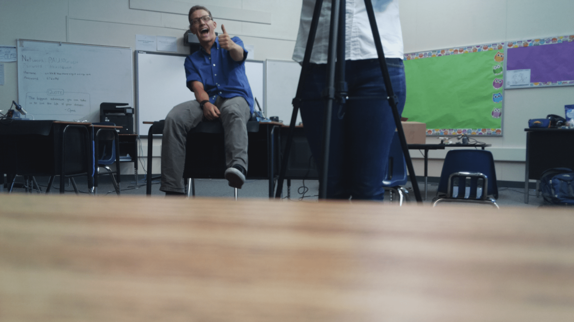
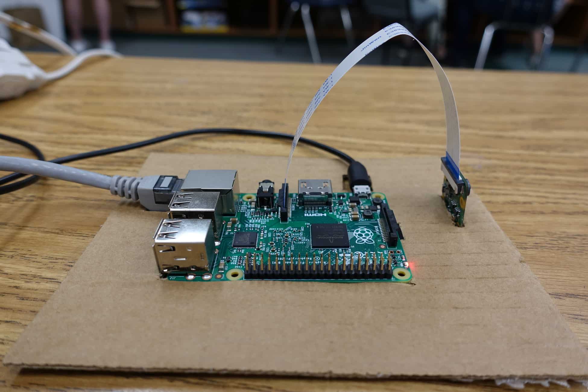
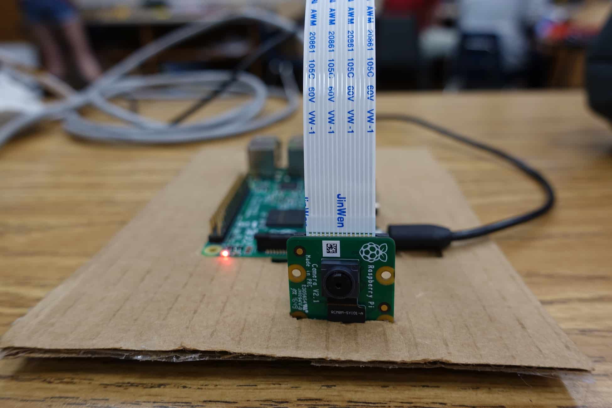
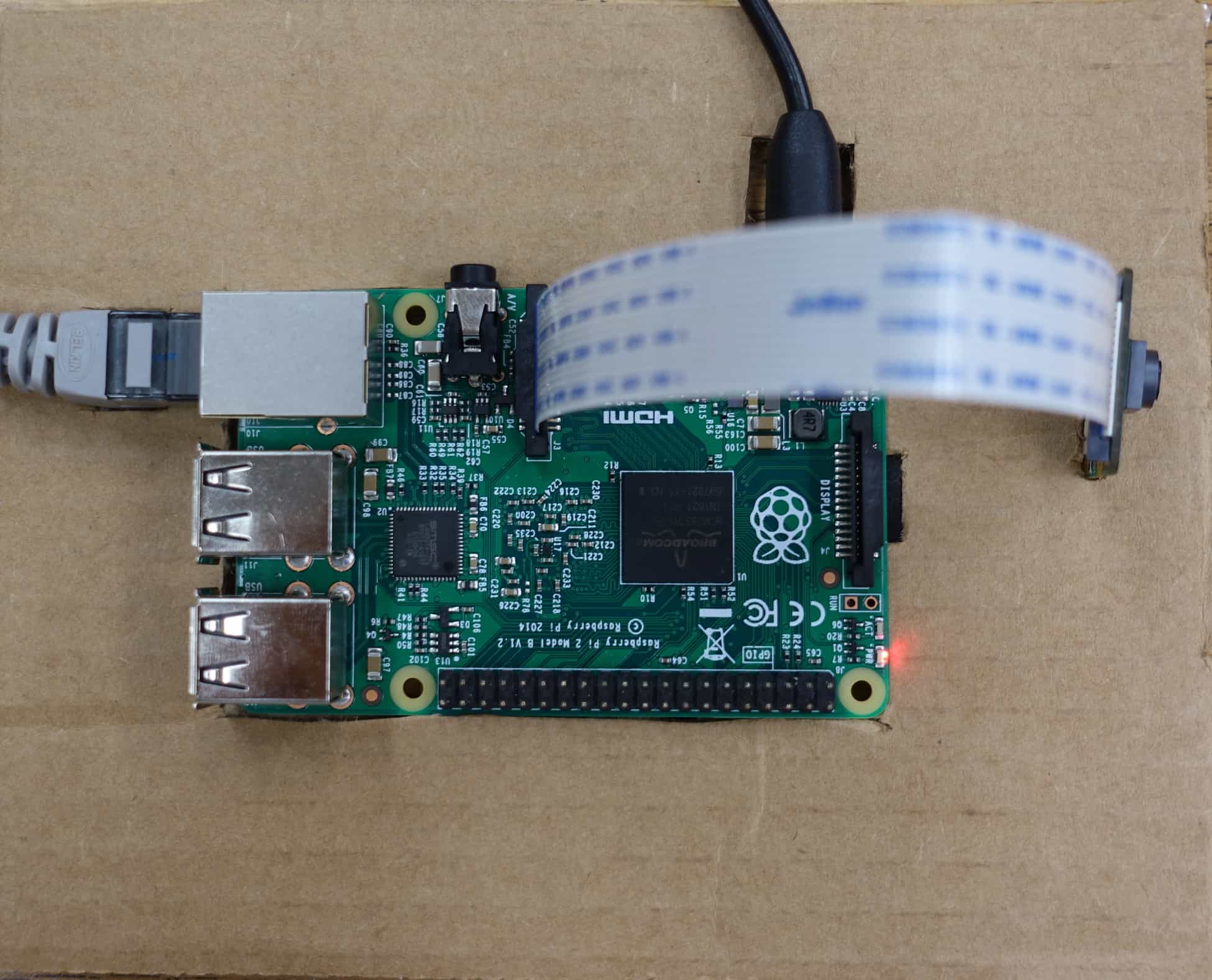
After all that installing and setting up, I made a cardboard base prototype with a hole the size of the Raspberry Pi, a hole to place the camera, and two more holes for the ethernet cable and microUSB charger because the cardboard got in the way of plugging them in the Raspberry Pi. Here’s some images my Raspberry Pi Camera Module has taken:
Here’s my simple cardboard prototype
Starter Project – Mini POV 4
I chose to make the MiniPOV4 for my starter project. I liked the idea that I would be able to create a picture in the air with the LEDs, and it also would give me the opportunity to work with electrical components.
The MiniPOV4 works by having the microcontroller chip store the image the LEDs create and the order the LEDs are supposed to flash. Instructions are then sent to three transistors to control the red, green, and blue values of all eight LEDs. The speed of the LED blinking is determined by the potentiometer and a quartz crystal acts as a timer. There are three capacitors that work to filter low and high frequency noise. There are also several resistors and they have varying purposes from controlling the brightness of the LEDs to making sure the transistors are protected from the microcontroller. The USB connector allows the MiniPOV4 to connect to the computer using USB connection, and the user can have the LEDs shine their own image they create.
Overall, this project was a good experience because it let me have a lot of experience with soldering and desoldering, and in order to understand how this MiniPOV4 functions, I gained more experience with researching online and digesting unfamiliar concepts. But the most fun part was definitely seeing the LEDs flashing correctly and the image that they produce.
Here are some pictures:


