
Hi! My name is Richard and I’m a rising junior at Benjamin N. Cardozo High School. The starter project I chose was the Exploding Star Light Organ. I chose to do this project because I wanted to work with different circuit elements and get some soldering practice. I chose the Omni-Directional Robot as my main project because of my interest in robotics, so I thought the best way to convey these interests was to actually build one. Before BlueStamp, I had very little to no experience in things like circuitry and coding, but after successfully completing both of these projects, I have a greater grasp on engineering as a whole. This program has given me great insight as to what I’d like to study in the future.

FINAL BOM: Bill Of Materials
———————————————————————————————————-
MILESTONE 3 (FINAL VIDEO)
For my third milestone, I successfully added an array of LEDs to my robot so that if I move my robot in a certain direction, a certain group of LEDs will light up. For example, if my robot moves forward, two blue LEDs will light up. If the robot moves backwards, two more blue LEDs light up. If the robot moves counterclockwise, a group of four white LEDs will light up. Additionally, I added a sticker to the roof of my robot, making the top of my robot look like carbon fiber. Afterwards, I also added shaft collars to the wheels to keep them secure (not included in video). One of the problems that I faced was that I didn’t have enough space on my breadboard to test all my LEDs, so I replaced my smaller breadboard with a bigger one and transferred all of my wiring to there.

———————————————————————————————————-
MILESTONE 2
For my second milestone, I built the structure of the robot using six steel bars to support the two layers of the robot. The two layers of the robot are both made of 8 inch regular hexagons that are also half an inch thick. I added the wheels to the bottom of the robot such that they were 120 degrees apart from each other, making the robot balanced on all sides. I placed all the wiring (Arduino, breadboard, etc.) onto the first level of the robot, making it easier to connect the wiring to my motors placed on the bottom. One of the problems I faced was how sometimes connections between the motors and Arduino would go haywire, leading me to attach all the wires to the wood using electrical tape so none of the wires can move around easily. For my next milestone, I plan to make modifications to my robot. I’d like to add LEDs such that when I press a different button on the controller, a different group of LEDs could light up.

MILESTONE 1

Here’s a schematic of how the circuit works, connecting the Arduino to the motors and PS2 controller.
Finally reaching my first milestone, I successfully connected my Arduino to my motors and my PS2 controller, being able to fully control the motors using the controller. How it works is that my battery sends power to both the Arduino and the motors. Once input is given from the PS2 controller, the controller’s receiver sends signal to the Arduino which in turn sends signals to certain motors and turns them in a certain direction, based on the button I press on the controller. One of the problems I faced was that, in my code, the pins on the Arduino board where I set to output signal didn’t match where I had attached my servos to the board itself, so I had to slightly configure the code because of that. For my next milestone, I plan to build the physical structure of the robot so it can move as one entity.

Here’s a 3rd angle view of what my robot will hopefully look like by its completion.
STARTER PROJECT
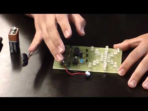
The starter project I worked on was the Exploding Star Light Organ. A 9 volt battery is used to power it. The purpose of the circuit is to light up different series’ of LEDs based on sound received by the microphone. When the microphone detects sound, it sends a flow of current to the 3 transistors located on the far right of the circuit, whom send an amplified current to the first IC chip. An IC chip or integrated circuit can act as an amplifier, oscillator, timer or microprocessor in a circuit. The first IC chip (IC 555) acts as a timer to send the flow of current into different electrical pulses and sends it to the second IC chip (IC 4017) which uses those electrical pulses to determine the order in which the LEDs light up. The other transistors act as on/off switches for each group of LEDs that lights up. The other transistors also amplify the current from the second IC chip to the LEDs so they can light up properly. The resistors (used to slow down current) and capacitors (used to store electrical energy) act as regulators for the flow of current. They also determine the timing sequence in the circuit, if the resistor and capacitor values are high the timing sequence is long and vice versa. The sensitivity of the microphone and the oscillation speed of the LEDs can be changed by twisting the horizontal trimmer resistors (P1 and P2).