About Me
Hi, my name is Ricardo and I am a rising Senior at Leadership Public Schools in Hayward, California. I have always been astonished by Engineering. Knowing how mechanical and electrical objects function, have always attracted my attention. I came to BlueStamp with no background knowledge what so ever, since my school doesn’t offer electives that are related to what I am interested into. Through my starter project, Laser Target Kit, I learned the process of: how to solder (following-up with desolder), and coding these were basic segments of my project and mostly for all engineering. Enrolling to a Program like this with hands on training, is where your future is shaped, and here I am, to start my own. Attending BlueStamp has given me the motivation and a huge commence towards my future.
I greatly think that BlueStamp has taught me what I am really passionate about. This summer program I feel that this would be a great start for my future. From learning of Soldering, to Coding, Hardware.etc. I learned that engineering is what I want to be. It was very challenging coming to this program with no experience and being nervous for worrying that I would be criticized. However, the tremendous help from the instructors and the life lessons from speakers that come in, is what makes this program great.
Final of Main Project: LED Wall Clock
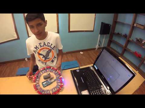

This is my final main project: an LED Wall Clock. It is functioning how I planned out since the beginning of the project. What I am strongly satisfied and proud of is the coding portion of my project, it rotates around the clock with each different color. The deal is done and crispy clean. I am more than satisfied, with the outcome of this project, I accomplished what I wanted it to be. Here’s a picture of the final result. One of my future modifications would be to create a screen to my clock.
My main Project mainly consists of coding and that was a great challenge for me. Coming to BlueStamp and creating something mainly focusing about code was a great experience. How did I make it happen? Well, I used the Library Time which I got from Github and is in a link under the Documentation tab. My LED Wall Clock is programmed with the seconds used since January 1st, 1970 and I managed to have the hours and minutes show. My RTC Chip was not included and used within this project because it was using the same data pin as the LED’s, which made my LED’s not light up. I assembled my Clock out of wood for my structure and cut it out myself. A 12 inch diameter and a 6 inch radius were my measurements to fit in 60 LED’s. Red signifies Hours, Blue Seconds, and Green Seconds. The LED’s go by fives and rotate clockwise. A 9Volt battery is a back up power source, so It would not always be plugged into the computer. Overall I truly feel accomplished and relived for doing something I wasn’t confident about.
Documentation
My project was based on these 4 step instructables. This is where my examples of code I needed were incorporated in, I just needed to comment and uncomment libraries. Here are the links I based my project on. Clock Pt. 1, Clock Pt. 2, Clock Pt. 3, & Clock Pt. 4.
I also used libraries such as the RTClib and Time+ for the programming of the time in my LED’s. Here are links to the code examples: RTClib and Time+.
This is my Final code for my RGB LED’s: Ricardo’s Github & Code
Bill of Materials: Here is the link to my actual Bill of Materials and what I ordered to actually make the clock: the direct links to the items are inserted aside it.
- 2 Strips of RGB LED Pixels WS2811, 12mm, 50 pcs
- 1 DS1307 Breakout Kit (RTChip: Real Time Clock Chip)
- 1 Arduino Leonardo or Arduino Mega.
Milestone 2
My second milestone mainly focuses on having my time mechanism organized and ready to go with my project. As you can see, I used my RTC Chip (Real Time Clock) to tell actual time and date, including: Hours, Minutes, and Seconds. With those components I was able to turn a single LED at the 1st second and command it to turn off once it reaches the 30th second. My serial port was a big part of my milestone because without it, I would not be able to track time, so with that, I can now substitute that LED with my LED strips for my clock. However, my LED strip does not support (DEC) and the RTC Chip, so I have to change my code to float, erase the RTC Chip code, and try to use a whole different library for my clock. Other than that, I would only need to work on hardware structure, in which I am trying to have wood as the main board.


This is a closer image of the RTC Chip (Real time clock) which basically is just like a watch. It runs on a battery and keeps time for you even when power goes off. Using an RTC, can keep track for long time parts. Next to it, micro controller Arduino Leonardo, where I use it with the RTC chip to tell the time. However, recently I have noticed that my Chip has been interfering with my LED’s and the SDA (Data Port) that my LED’s also use. So I had to not use my Chip, and fix my code, (Time Library).
(learn.adafruit.com)
Milestone 1
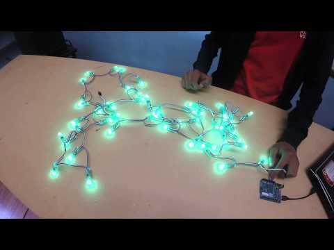
My first Milestone consists of Lighting up my LED’s using Arduino Library LED Master and my for loop code. Here my For loop, I constructed it myself with help of my instructor and well-explained the functions of it to me. For the LED code, I used GitHub for the necessary program and examples needed. Here is the site, if you would like to see the code with its examples (FastLED). By using my for loop and a different serial port code (time) that I created with the help of an instructor, having to tell seconds, minutes, and hours, my LED’s are ready to be used with my RTC Chip. Now that I have my RTC Chip (Real Time Clock) which is my mechanism to have the correct time, I will use both to command my LED’s when and where to light up. Throughout the process, the programming section of my project is almost coming up to an end.
Starter Project
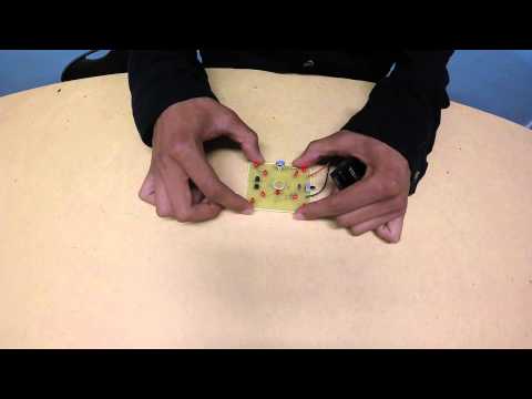
My Starter Project was the Laser Target Kit. It is a project that consists of 9 red LED that are lightened up by any source of light when touching the Light sensor ( CDS Cell) to turn on the LED’s. The way it functions is by a 9V battery and three switches ON1, OFF, AND ON2 and a 5K Vertical Trimmer Resistor that is like an obstacle to block current to one of the LED’s. ON1 only has one LED powered off because of the trimmer resistor that blocks sort of the gate to trespass current (light). ON2 when switched has all LED’s functioning, but when the trimmer resistor is being moved, all but one LED is turned off and that one LED is the one from ON1. Any sort of light given to the light sensor (CDS Cell) will make the LED’s function, powering the LED’S.


The 9volt battery is the main power source for this project. It runs current throughout the LED’s, resistors of 1k is what blocks the current from going to one LED.This Is how my Starter Project looks like from a Close-Up View. Here’s also the link to my project, Laser Target Kit, the instructables that I worked with are inside the kit.
(goldmine-elec-products.com)
Here Is a little demo of my Starter Project and how it works. Since I didn’t have an actual laser to turn on/off the light source, I decided to use my finger for a better example and view to block the light source.
Pretty cool stuff Ricardo. Keep up the good work. Hope you are having fun and looks like you are learning a ton.
Nice Ricardo! Hope you reach your goals! Keep up the good work.