Line-Following Robot
The line-following robot uses IR (infrared) proximity sensors that sense a black line, and then send a signal to motors that make the robot move and follow the line!
Engineer
Rhea P
Area of Interest
Bioengineering/ Electrical engineering
School
Trinity School
Grade
Rising Sophomore
Reflections
I feel that from instruction at Bluestamp I’ve formed a really solid foundation that I can use to move onto some more independent projects. I’ve found that engineering ignites a drive within me to keep pushing through any problems I face, and I am now more open than ever to immersing myself in anything that will expand my knowledge. I’m actually looking into getting an introduction into bioengineering, after hearing from successful engineers and entrepreneurs who’ve spoken during this program! I would love to dive more in depth into that with the basis of electrical and mechanical engineering I’ve formed in this project. This Bluestamp experience only reconfirmed the amazing times I had last year in the on-site program, and I’m really glad I was able to dive into more programming, motors, and sensors!
Scroll Below for more Videos and Explanations!
- 2 wheel car chassis kit (two 3V-6V DC motors are included): link to buy here!
- Infrared Proximity sensors: link to buy here!
- L298N Motor Driver: link to buy here!
- Jumper wires: link to buy here!
- Power sources:
- I used a 9V alkaline battery to power the motor driver
- I also used four 1.5V alkaline batteries (6V total) to power the IR sensors
- Breadboard (for first stages of project): link to buy here!
- Perfboards (for soldering modifications): link to buy here!
Final Milestone
I made modifications and built on the finish base project for my Final Milestone. I initially added a Servo Motor that would raise a small flag when the robot was in motion, but it turns out that little Servo took away some power from the sensors and really hindered my robot’s function. Instead, I took my circuit off the breadboard, and turned to soldering all the wires in place to perf boards as a modification. I also glued the IR sensors in place so they wouldn’t continue slipping and altering the robot’s path.
Code for Robot (using Arduino IDE software)
Second Milestone
In my Second Milestone I attached the IR (infrared) proximity sensors to the chassis and breadboard. They work by sending out infrared light, and sense if something is in front of them if they sense infrared rays bouncing back towards them. So, when the robot “follows” a black line, they’re just signalling the motors to move forward when they don’t receive an infrared signal back, (because black absorbs the infrared rays and does not reflect them back to the sensors.) I also coded the IR sensors to control the motors, which is essentially my project. I basically made this code with code I found online for the sensors and code I found for the motors, and mushed them together. I got the sensors to control the motors in this way using “if” and “else if” functions
-
- For example, IF both sensors do not receive signals (if its on a black line), then the wheels move forward
- ELSE IF one sensors does not receive signals , and the other one does (if one is on the black line and the other one isn’t), then the robot turns one way or the other
- ELSE IF both sensors receive signals (if it’s no longer on a black line), then the robot stops
//defining pins and variables
//Motor A connections
int enA = 9;
int in1 = 8;
int in2 = 7;
// Motor B connections
int enB = 3;
int in3 = 4;
int in4 = 2;
void setup() {
//declaring pin types
pinMode(12,INPUT);
pinMode(5,INPUT);
pinMode(enB, OUTPUT);
pinMode(in3, OUTPUT);
pinMode(in4, OUTPUT);
pinMode(enA, OUTPUT);
pinMode(in1, OUTPUT);
pinMode(in2, OUTPUT);
//begin serial communication
Serial.begin(9600);
}
//for sensor: 1=black=nothing=move, 0=white=something
void loop(){
//printing values of the sensors to the serial monitor
Serial.print(“IRSensorip “);
Serial.println(digitalRead(12));
Serial.print(“IRSensorip2 “);
Serial.println(digitalRead(5));
//establishing motor speeds
analogWrite(enA, 200);
analogWrite(enB, 200);
//line detected by both
if(digitalRead(12)==1 && digitalRead(5)==1){
//Forward
digitalWrite(in1, HIGH);
digitalWrite(in2, LOW);
digitalWrite(in3, HIGH);
digitalWrite(in4, LOW);
}
//line detected by left sensor
else if(digitalRead(12)==0 && digitalRead(5)==1){
//turn left
digitalWrite(in1, HIGH);
digitalWrite(in2, LOW);
digitalWrite(in3, LOW);
digitalWrite(in4, HIGH);
}
//line detected by right sensor
else if(digitalRead(12)==1 && digitalRead(5)==0){
//turn right
digitalWrite(in1, LOW);
digitalWrite(in2, HIGH);
digitalWrite(in3, HIGH);
digitalWrite(in4, LOW);
}
//line detected by none
else if(digitalRead(12)==0 && digitalRead(5)==0){
//stop
digitalWrite(in1, LOW);
digitalWrite(in2, LOW);
digitalWrite(in3, LOW);
digitalWrite(in4, LOW);
}
}
First Milestone
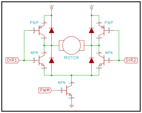
Assembling the robot car chassis with a motor circuit for the robot to make it move was my first milestone. That motor circuit contains the L298N motor driver, two 3V-6V motors, and an Arduino microcontroller. The L298N motor driver uses PWM (pulse width modulation) pins and an H-Bridge circuit to control the speed and directions of the two motors. PWM pins basically turn the power on and off super quickly, which allows you to adjust the average value of the voltage coming from the pins to control the speed of the motors. An H- bridge circuit is one that contains four different elements (transistors or MOSFETS) that control the rotation direction of the motors. It does this by activating two particular elements at a time to switch current flow, which therefore changes the rotation direction. his motor driver is connected to an Arduino, which is an open-source computing platform that receives inputs from code or other pieces of hardware and turns them into outputs.


