Reflection
I learned so much from my Bluestamp experience, and it has inspired me to pursue even more opportunities in engineering! I have not had a whole lot of past experience with coding and engineering, and now I can build off of a strong foundation cemented at Bluestamp.
Final Milestone
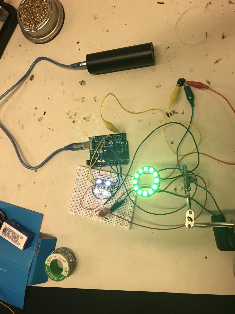
So here’s my final milestone! For this, I connected the Neopixel ring to the color sensor, and added a button that connected to the Arduino. Essentially, here I added some code from a Neopixel library example into the code for the color sensor, so whenever the sensor sensed red, green, blue, purple, or yellow the Neopixels lit up in that color! I looked up the RGB values of a generic red, green, blue, purple, or yellow color, and input that into my code. My chameleon is not exactly sensing the exact shade of the color of the object I put in front of it, but sensing a generic range and classifying it as a certain color, which then correlates to red, green, blue, purple, or yellow lights. Then I also added a pushbutton, so the color sensor only works when the button is held down, and then the LEDs stay the same until another color is sensed. So thats the chameleon!
First Milestone
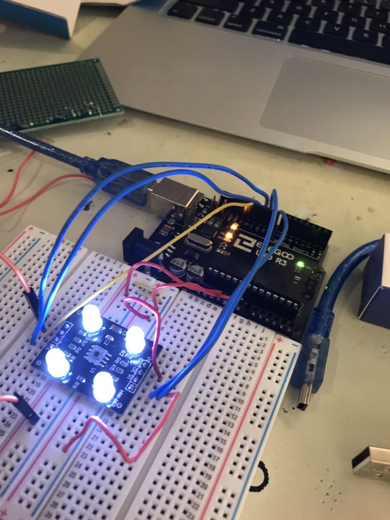
This is my first milestone! Here, I connected the TCS230 color sensor to an Arduino Uno. A little setback was the fact that I can’t really use an Arduino Nano with my computer, but as long as it works with some microcontroller, I suppose that’s alright! I followed the pin connections for connecting an Arduino to the color sensor that were listed in an example code, but I had to make a few minor edits to make it how I needed. The code sensed the basic RGB values, and only red, green, and blue. Using the RGB values display in the serial, I made ranges using inequalities for the R, G, B values of five colors. Then, if the sensor sensed RGB values that conformed to one of the colors, it printed __color in the serial console. Here’s a little bit about how the TCS230 color sensor works:
- It has 16 photodiodes with a red filter
- It has 16 photodiodes with a green filter
- It has 16 photodiodes with a blue filter
- It has 16 photodiodes with no filter
The red filter photodiodes are sensitive to red wavelengths, the blue filter ones to blue wavelengths, et cetera. Light hits these photodiodes, there is a current to frequency converter in the sensor, and the output is transmitted to the Arduino.
Thats my first milestone! The next steps are to connect this to the Neopixel ring!
Starter Project
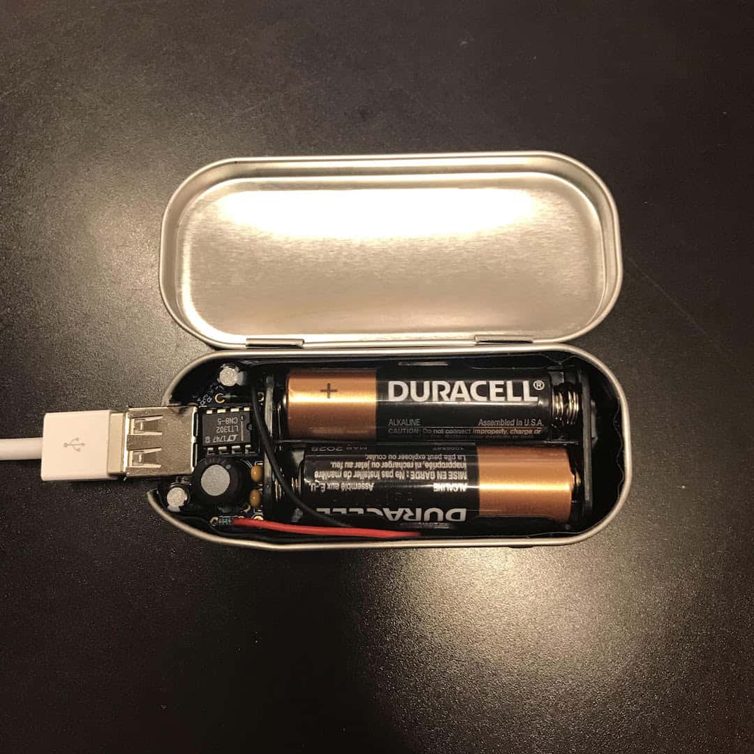
My Starter Project is the Mintyboost 3.0 Portable Charger. It runs on two 1.5 V AA batteries, using a boost converter to charge a phone that uses a 5V charger. It’ll probably keep my phone from dying on me 🙂
Mintyboost!
How it works
Some important components of the Mintyboost are the
- Boost converter
- The inductor
- The electrolytic capacitors (helped by the ceramic capacitors)
- The diode
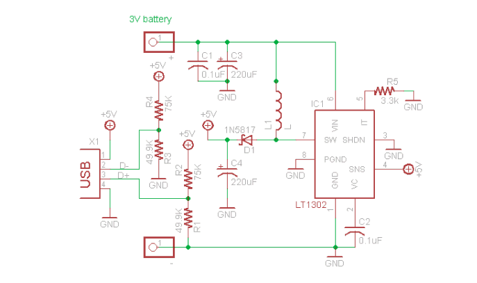
For my iPhone, the charger uses 5V, but the Mintyboost runs on two 1.5 V AA batteries. This is why I need a boost converter, to convert the 3V from the batteries into 5V that the charger uses. In the circuit the current runs through the inductor. When current runs through an inductor it creates a magnetic field around the inductor. A boost converter uses a transistor to turn part of the circuit on and off at a very high speed. When the magnetic field around the inductor collapses when the boost converter switches off the current from the batteries, a high voltage spike from the magnetic field itself is generated. This quickly goes through another part of the circuit through the diode and is stored in the capacitors. The diode prevents the current from going back to the power supply. Every time there is a voltage spike from the inductor’s magnetic field, more current is stored in the capacitors, stepping up the voltage. This way the 3V from the power supply is converted into 5V for the charger.
Mintyboost 3.0 Schematic


