Reuben L.
My name is Reuben. I am a rising senior at Fiorello H. LaGuardia High school. I chose the Bubblesteen Bubble Machine, a bubble-blowing robot. I chose this project because I wanted to get more exposure to the programming side of engineering, while still keeping my feet planted in mechanics. I chose the Mini POV peoject from Adafruit as my starter project, because I was drawn to its simplistic, artistic beauty.
Engineer
Reuben L.
Area of Interest
Undecided
School
LaGuardia High School
Grade
Senior
Reflection
I learned so much in my process of building the Bubblesteen. I learned how to teach myself new fields of engineering, like working with a shift register.
The Bubblesteen Bubble machine helped me to understand myself as an engineer, and to be comfortable with the world of engineering. It also helped me be less afraid of failure; the Bubblesteen process was strewn with failure after failure, leading eventually to a success. As Jerry Seinfeld said, “Keep your head up in failure and your head down in success.”
FINAL PROJECT
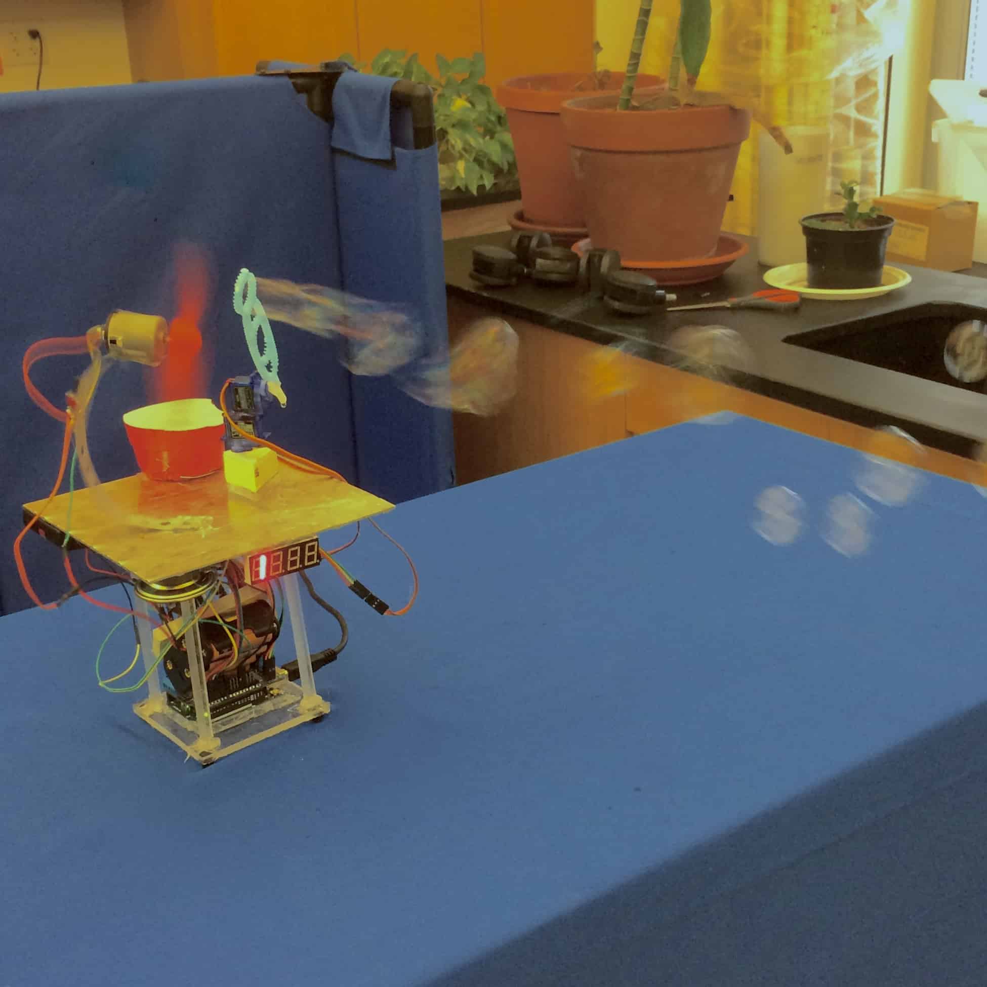
The most difficult part of the last few stages of building the Bubblesteen was making sure that the bubble wand could effectively dip into the bubble fluid. In order for bubbles to be blown, the wand had to be able to submerge its tip completely in bubble fluid. The fluid cup had to be specially engineered to be the perfect size. Too large and the wand wouldn’t be able to fit in; too small and it wouldn’t hold enough fluid to completely submerge the wand. This task proved to be much easier after the wand system was elevated a quarter inch higher, on a cut piece of acrylic.
The other major achievement of the final stage of this project was getting the fan motor to spin quickly enough. In the previous stages, it had been impossible to blow bubbles with the motor controlled by the Arduino; it was too weak. The solution to this problem was simple. I separated the motor from the Arduino completely, and I replaced its power source with two 9v batteries connected in parallel. I also added a switch. This proved successful. The motor was strong enough to blow bubbles. It was somewhat inconvenient, however, because the two components of the robot worked separately only.
My first mod plan was to make the bubble machine wifi-controlled, but lack of access to reliable wifi without a login showed that to be impossible, or at least in need of a postponement. Instead, I focused my work on making the bubble machine into an alarm clock, that would wake me up with bubbles. There were two main concepts that I had to learn in order to accomplish this task: one, how to make a clock display, and two, how to keep time on an Arduino with an RTC.
The clock display was interesting, and not too difficult. The display had 12 pins: eight controlled each digit’s eight segments, and the remaining four would establish which of the four digits were receiving the image the eight determined. The pros of this 12-pin system is that it keeps the number of pins needed to a minimum, but unfortunately it also means that only one unique number can be displayed at a time. To circumvent this setback, I had to have the computer send its four-digit numbers one at a time. Luckily, persistence-of-vision made the display on the module look fluid and normal.
I wrote a simple counting code in order to get acquainted with the display. Each digit increases its value until it reaches 10, at which point it reverts back to 0 and alerts the next digit in line to increase by one. Once I saw it working, I felt ready to move on to controlling the display with an RTC.
But before I could, I was given an assignment. I was told to try to control the display with a shift register. Including this component would complicate the process of building a clock, but it would make it so that only three digital output pins on the Arduino would be necessary to control the whole clock.
To control the shift register, I had to become well acquainted with the shiftOut() function. It controls a shift register with four parameters: dataPin, clockPin, bitOrder, and value. DataPin and clockPin are the Arduino output pins that control the shift register. BitOrder just determines direction: Does the value enter the register headfirst or feet first? This is important, because the shift register sends data out of its eight output pins by giving the information to the first pin, and sending its instructions down the line. Finally, value refers to a number between 0 and 127 that will determine the output the shift register gives. (With eight output pins, the shift register has 127 different combinations of ons and offs.) The number is translated into its binary code, and the eight digits of this binary number are assigned to the eight output pins on the shift register.
After figuring out how to send different arrangements of ons and offs to the shift register, I had to figure out how to turn the contraption at hand into a clock. It wasn’t as hard as it seemed: All I had to do was create four different variables, in the code: one for each of the four digits in a digital clock. Then, getminute() and gethour() were used to determine the values of these variables.
Finally, I had a clock. It was stationed on a breadboard, and I wanted to transition it to something more solid, but soldering the thing to a PCB proved an overly complex task. I settled for the breadboard.
The next obstacle I had to surmount was connecting the two projects – the clock and the bubble machine – to each other. The problem with this, I believed, was that the servos and the clock occupied the same digital pins on the arduino, and the problem with this problem was that it was not clear which pins the servos were connected to. However, even changing the pins I was using did not seem to solve the problem.
I decided to keep building the project regardless. The problem would not interfere with the function of the project very much, because the clock part and the bubble-blowing parts of the machine did not often work at the same time.
The project was completely finished apart from this problem, so I decided that the trouble this problem caused me could be considered insignificant enough to ignore, at least for now.
I encountered another problem afterwards: The motor and propeller I had set up did not spin quickly enough and with enough force to blow bubbles at all. They once had, but since then I had switched out the motor for a weaker one.
At this point, I had two 9v batteries, in parallel, attached to a BJT that was controlled by the Arduino. I tried attaching them in series instead, but that didn’t work. My next idea was to replace the propeller with a more efficient one, but even this couldn’t get it to spin quickly enough.
For my final presentation, the motor was controlled by a switch. Unfortunately, the machine would have to be controlled by the Arduino in order to function as an alarm clock. My work was not done.
Getting the Arduino to control the motor was so difficult because few BJTs or FETs are capable of handling the immense voltages I asked of them. To finish this project, I might have to experiment with a Relay – a kind of electronically-controlled switch.
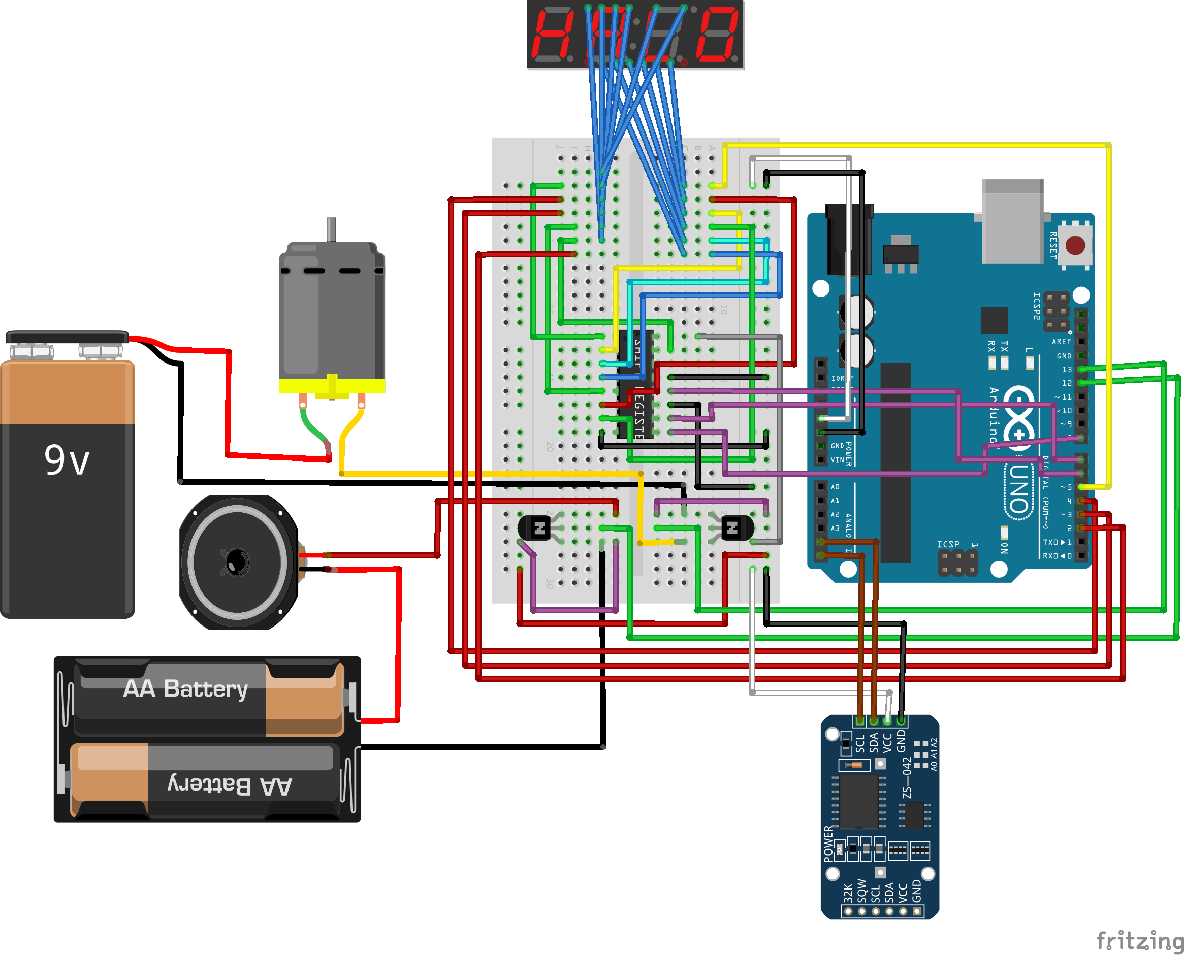
My final schematic
Documentation
My code and schematic:
https://github.com/reubendsk/Bubblesteen-code
The fan I used, download from Thingiverse:
https://www.thingiverse.com/thing:4243
Bill of Materials: