
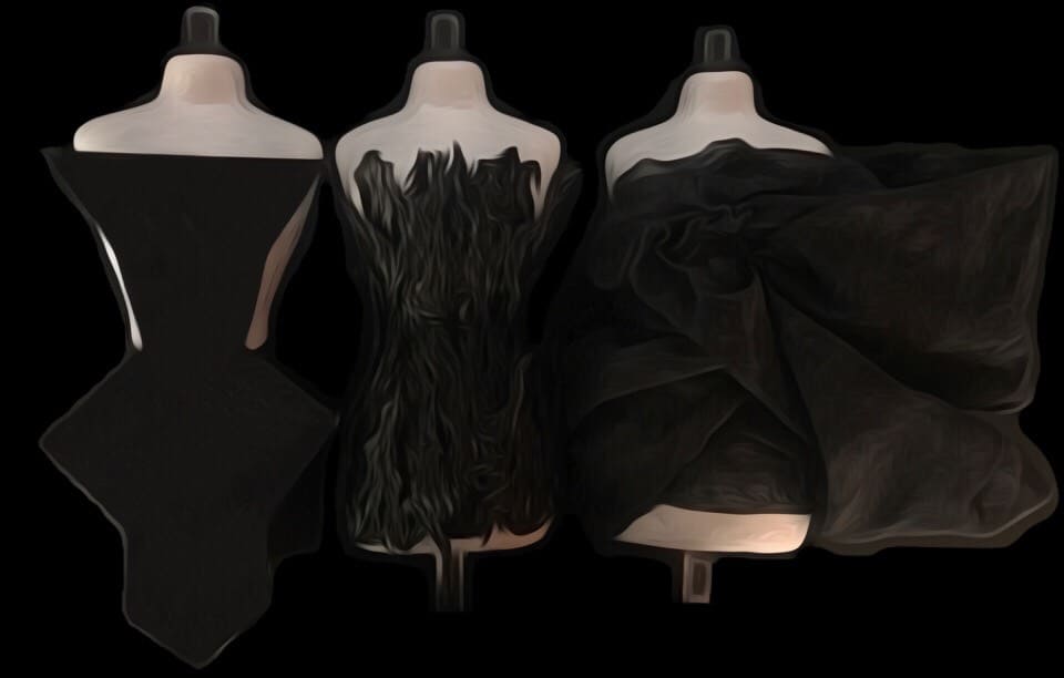
a 3D printed thermochromic dress concept
This project entails the development of three concept dresses. In my first dress design, I combined both elements of 3D printing and thermochromic dyed fabrics, which are fabrics that change color when heat is directly applied. There are two layers to the fabrics: organza fabric painted with thermochromic ink (top) and conductive heater fabric (bottom). Using wires soldered onto the sewn pins on the back of these pads, the heater fabrics are connected to the Arduino Flora. The Flora along with an N-channel MOSFET controls the amount of heat being passed to the heater fabrics, and thus controls the rate of when the fabric changes color. My second dress is completely 3D printed with the Ninjaflex filament on the Makerbot Replicator 2 printer, and my third dress is completely made up of the thermochromic dyed fabrics. Micro servos are sewn into the fabrics of this third dress to give the effect of the fabrics moving. The movement of these microservos are activated by the movement of my fingers; using a Bluetooth connection with the NRF24L01, the flex sensors and Arduino UNO sewed on gloves communicate with the Arduino Nano and micro sensors in the dress.
My inspiration for the design of these dresses were drawn from nature. I studied several species of flowers such as the Anguola uniflora, the Strongylodon macrobotrys, and the Caleana major to create my first dress. My second dress is the manifestation of studying the shape and curves of flames and waves, and my third dress is my interpretation of mist and fog.

NYC!
Thank you for the never ending love and support in making my vision come to life! I’m so grateful for this personalized learning experience; I have grown so much over these past six weeks as both a work study intern and a student. I’m so grateful for this opportunity to combine both my passions of fashion and engineering into a project I can call mine.
This project has really immersed me in everything; from programming in the Arduino IDE, to soldering wires, to reading data sheets and schematics, to checking current and voltage with a multimeter, to material testing with 3D printing, to reiterating dress designs, I have really learned so, so much.
what my project is
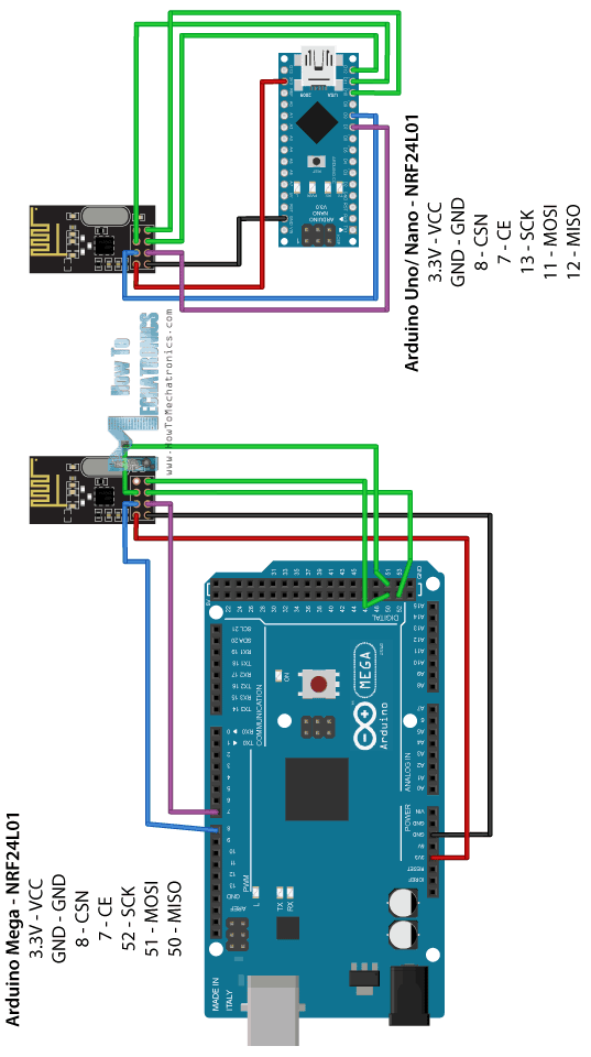
For my third milestone, I created a second and third dress. The second dress is completely 3D printed and the third dress is completely made of the thermochromic dyed fabrics. This milestone focused on developing my third dress into something more; I experimented with flex sensors and micro servos to literally bring the dress to life; I sewed both ends of the micro servos into the fabric of the dress so that when the micro servos are activated, the micro servos “grab” onto the fabric and twist, then unfurl. This movement of curling and uncurling is looped continuously. At first, I simply had the micro servos moving with just the flex sensors and the Arduino UNO, but because I wanted something more interactive, I added the NRF24L01 and glove aspect so that the dress would move in correspondence to my hand movements.
how it works
The Arduino UNO and flex sensors on the glove communicate with the Arduino Nano and micro servos in the dress through the NRF24L01, which establishes a Bluetooth connection between the two sides.
lessons i learned
I continued to further my knowledge in programming in the Arduino IDE, and I learned how to connect two hardware components with a Bluetooth connection. I also understand micro servo movements now and that there is a difference when it comes to programming a regular micro servo and a continuous micro servo. I had never worked with flex sensors, the NRF24L01, or the Arduino Nano before, so these hardware pieces’ pinouts were something I learned to understand as well.


what my project is
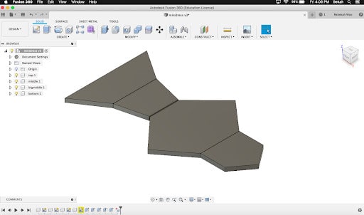
For my second milestone, I CADed, 3D printed, and arranged all of the parts of my dress onto a mannequin. The CAD design of my dress is very simple: it consists of multiple different sized trapezoids and pentagons arranged into a dress shape. I first prototyped my design, cutting out the shapes with cardboard, to make sure all my dimensions were accurate. Once I was confident about my dimensions, I replicated my design onto Autodesk Fusion 360. From there, I went on to 3D printing. 3D printing was the biggest roadblock for this milestone. I ran into several problems with the Ninjaflex filament with the Makerbot Replicator 2. The filament would sporadically extrude, the filament would not stick onto the build plate, or the filament would be extruded out too thin. Because of this, the scale my project works on is a seven inch mannequin. I researched ways to fix these problems and found that by changing a few settings, the printer would extrude the filament out more consistently. I lowered the retraction speed to 1mm, raised the temperature to 250 degrees Fahrenheit, slowed the solid print speed to 10mm/s and the sparse print speed to 20mm/s. I also releveled the bed to be closer to the plate.
While these changes minimized the problem at the beginning, the printer was unreliable after four successful prints. The printer would print the first layer, but then not extrude at all after this first layer.
I realized the printer would heat up to 250 degrees Fahrenheit, then drop to 230-240 degrees Fahrenheit after the first layer. However, the Ninjaflex mentioned only prints at 250 degrees. To fix this, I downloaded the old Makerbot software version: Makerbot Desktop. Despite being the older and unrecommended version by Makerbot, this Desktop version allows me to turn off “Active Cooling” in the settings, and I actually have more control over more settings with this version. Turning off the active cooling setting dramatically helped. To display the dresses, I drilled three 0.5 inch holes into the lid of a black project box to hold the mannequins, and stored the wires and Arduino inside.
how it works
On the Makerbot Replicator 2 printer, the Ninjaflex filament needs to print at 250 degrees Fahrenheit; if it is any lower than 250 than the extruder will not be hot enough for the filament to extrude. If it is any hotter, the filament will ooze out onto the print while it is traveling. Lowering the retraction distance , and slowing down the print speed (both solid and sparse) allows time for the filament to fully extrude out at each point in the print. Turning off the rafts and bridges speeds up the overall print time.
lessons i learned
This milestone has taught me a lot about each printer setting and how it affects a print. I have also learned parts of the 3D printer hardware since I had to constantly unscrew and screw back on the extruder and fan to unclog the printer.
what my project is
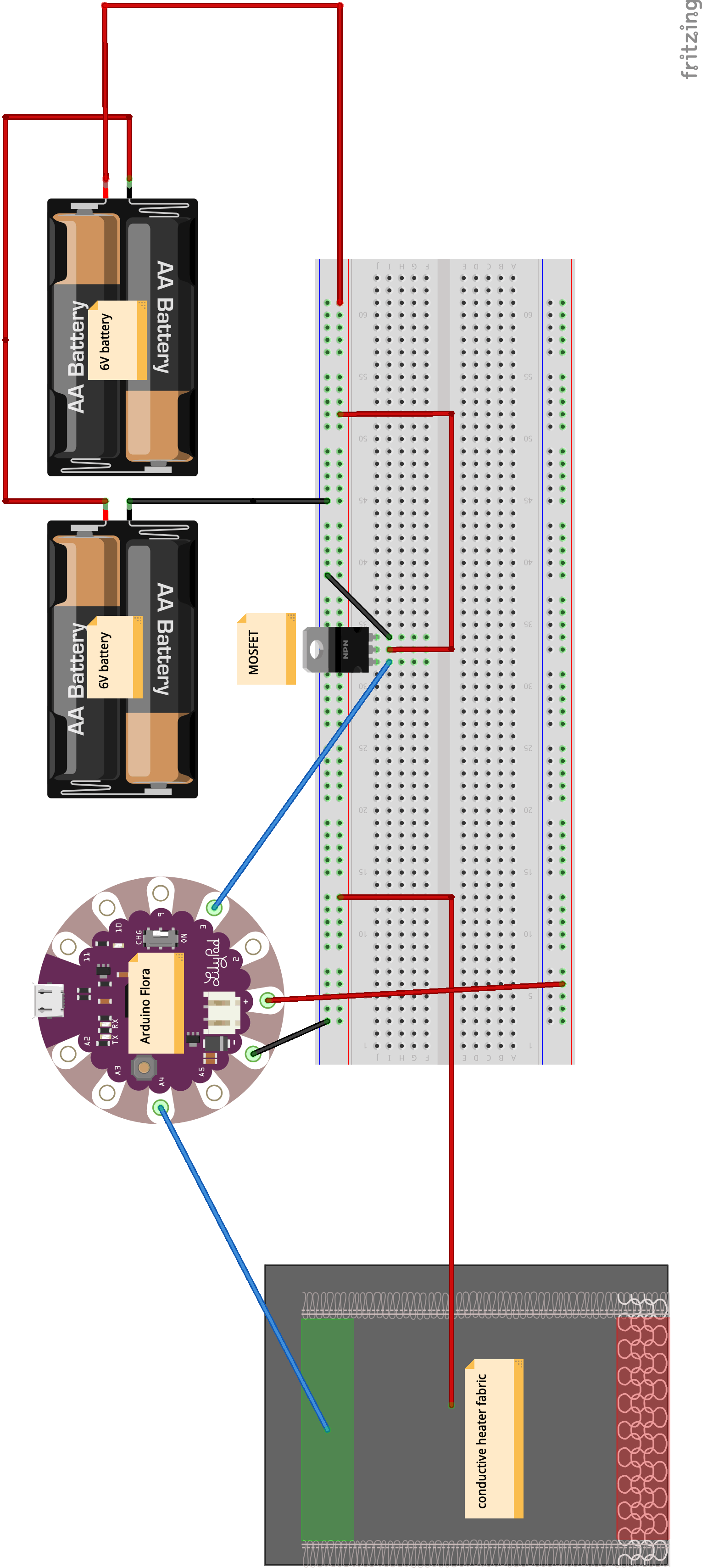
For my first milestone, I prototyped a single panel of my dress with cardboard. To control the amount of heat flowing to the conductive heater fabric, I experimented with MOSFETs, operational amplifiers, and transistors, building a different arrangement with each. I ultimately chose to implement the arrangement with the MOSFET because it was the easiest for me to control. There are three layers to my panel. On the bottom is the cardboard, which will be replaced with the 3D printed panel in the final design. Above the cardboard is the conductive heater fabric. This fabric has 20Ωof resistance and is filled with conductive material that can make the fabric emit heat when powered. Finally, on top of this heater fabric is the fabric dyed with thermochromic paint. The fabric changes color when heat supplied from the heater fabric powers on. This heat is controlled by the MOSFET and the Flora. The Flora simply supplies the power for the MOSFET to manipulate. The MOSFET has three parts: gate, drain, source. The 12V power is connected to the drain, the ground is connected to the source, and the gate is connected to the Flora. The gate controls the movement of electrons which then controls the current flow through the channel between the drain and the source and there is no current flow from the gate into the MOSFET; it’s basically an electronic switch.
how it works
Operational Amplifiers: The Op-amp comparator compares one analog voltage level with another analog voltage level and produces an output signal based on this voltage comparison Basically, the op-amp voltage comparator compares the magnitudes of two voltage inputs and determines which is the largest of the two.
MOSFET (metal–oxide–semiconductor field-effect transistor): The MOSFET is a voltage controlled electronic component that acts as a switch. You connect a circuit using the drain and the source as switch connections. The circuit completes when the channel is formed and drain to source conduction starts. To make the channel, I have to apply a sufficient amount of voltage (greater than threshold) to the gate. When it’s below this threshold, it is off. So this is how switch can be controlled.
Transistors: A transistor conducts current across the collector-emitter path only when a voltage is applied to the base. When no base voltage is present, the switch is off. When base voltage is present, the switch is on. Transistor will be in OFF when the input Vin equal to zero. During this state transistor acts as an open circuit and thus the entire voltage Vcc will be available at collector. Transistor will become ON when a sufficient voltage V is given to input. During this condition the Collector Emitter voltage Vce will be approximately equal to zero, ie the transistor acts as a short circuit. Thus collector current Ic = Vcc/Rc will flows.
lessons i learned
This first milestone has taught me so much about MOSFETs, transistors, and operational amplifiers, and I’ve also learned how to apply Ohm’s law, the relationship between resistance, voltage, and current in the real world.


what my project is
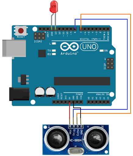
For my starter project, I built an Arduino program where the closer an object is to a sensor, the faster a light blinks. By using an ultrasonic distance sensor HC-SR04 and a light emitting diode (LED), I am able to control how fast an LED blinks in response to how close an object is to the HC-SR04. The reading on the sensor goes to the micro controller, which controls the LED blink rate with respect to the distance between the sensor and an object in front of it.
how it works
My entire project consists of five hardware components: an open-source microcontroller board (Arduino UNO), a base for prototyping (mini breadboard), wires with connector pins at each end (jumper wires), a device that can measure the distance to an object by using sound waves (ultraSonic distance sensor HC-SR04), and a light emitting diode (LED). Connecting the Arduino UNO and mini breadboard with jumper wires allows the components on the breadboard, the sensor and the LED, to communicate with the Arduino. The trig pin (speaker) on the sensor sends a signal, and when this signal detects an object in front of it, it is reflected back to the transmitter, where the echo pin (microphone) receives it. The sensor then converts this time between the transmission and reception of the signal into a distance. Finally, this distance converts into a time: the delay time the LED blinks. This process, sending and receiving signals, loops continuously.
lessons i learned
This starter project has really taught me the basics of Arduino and its functions. Because I have never worked with an Arduino before, I gained a lot: I learned the main components of an Arduino, the Arduino IDE syntax, and how an Arduino communicates with a breadboard.


name — rebekah w.

school — canyon crest academy

grade — rising senior

area of interest — 3D printing mechanical engineering design polymer chemistry