Solar-Powered Automatic Plant Watering Device

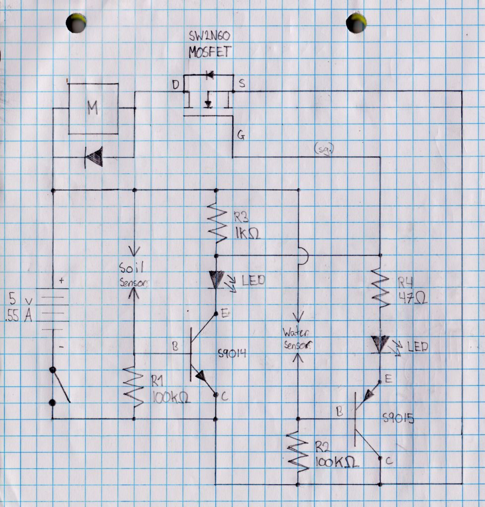
My project is a device that can automatically water a plant.  The device uses a circuit with soil and water sensors.  The circuit can turn off the water pump when the soil is wet and turn on the water pump when the soil is dry.    The device is also modified to use solar power.  To do so a Lithium Ion Polymer battery, Lithium Ion Polymer battery charger, and solar panel are attached to power the circuit.

Engineer

Rebecca M.

Area of Interest

Computer Science

School

SAR High School

Grade

Incoming Senior

Reflection

BlueStamp has taught me some very important skills for engineering and life in general.  Learning how to problem-solve and troubleshoot were very important in building my project and are useful skills for many fields. Each issue I encountered was somewhat frustrating but also valuable as I took many steps to resolve it.  Also, taking the time to write and record my different milestones taught me the value of documentation.   Documentation is helpful for both me and others who wish to build the same project. We also heard from many guest speakers, including entrepreneurs and innovators, who are a great source of inspiration for various paths I might choose to pursue in the future.

Final Milestone

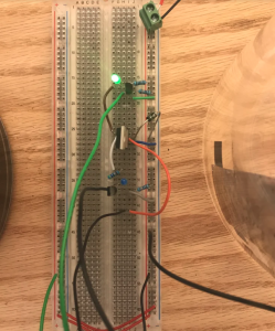
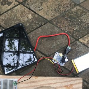
For my final milestone, I finished building the circuit and attaching the pump. I attached the tubing to the water pump using a hot glue gun. I also tested it a few times to fix any leaks and make sure it is airtight. I decided to use the breadboard for the final circuit. Using the perfboard was very difficult for this circuit because of the amount of close connections. I tested each connection using the continuity tester on a multimeter. Some connections were too close and current was flowing through parts it shouldn’t, causing the pump to always be on. I tried building the circuit more spaced out on a new perfboard but the pump also would not turn off when the soil was wet. Therefore, I went back to using the breadboard because it is easier to move the connections around and test if the circuit is working properly. Now the pump works properly and turns off when the soil is wet.  I cut a wooden board to attach to the containers and breadboard. I also modified the project to be able to use solar power instead of a normal 5V power supply. To do this, I hooked up a 3.7V/4.2V Lithium Ion Polymer battery to a Lithium Ion Polymer charger. The Lithium Ion Polymer charger includes one capacitor to help store the charge. It can also be connected to a 6V solar panel to draw energy from the sun. Since the Lithium Ion Polymer battery provides around 4V to the circuit and the solar panel up to 6V so there will never be a shortage of electrical energy. When it is dark out, a power supply can be plugged directly into the charger’s DC jack to power the device. While building this project, I learned the importance of trial and error through adjusting and testing the circuit many times to get it to work. The more careful you are while building the circuit, the less troubleshooting and fixing will be necessary so take your time.

First Milestone

For my first milestone, I am testing my circuit on a breadboard to ensure it works properly before soldering it onto a perfboard. The device utilizes a circuit to make sure the device only waters the plant when the soil is dry. See diagram below. The breadboard is connected to a 5 volt power supply to power the circuit. There is one soil and one water sensor electrode. These are both made of aluminum foil and are sensitive to moisture. Because of this sensitivity, when the soil is dry and when there is water in the reservoir, the motor will be powered. To implement the sensors into the circuit, two wires are connected to each using binder clips. If the water reservoir is empty it will pose high resistance because there is no water allowing electrons to flow easily. Similarly, if the soil is dry it will also pose high resistance because it is also more difficult for electrons to flow without water.  The circuit powers a water pump which will later be connected to a tube to transfer water into the plant container. The circuit utilizes a MOSFET transistor to turn on the pump only when the soil is dry. The MOSFET transistor has an insulated gate which can control conductivity based on the amount of applied voltage. A MOSFET works electronically like a switch. It varies the width of the channel where current is entering based on the voltage and can close the drain where current exits. In my circuit, the MOSFET is connected to the motor and sensors. Therefore, the MOSFET closes and opens the channel to supply power to the pump based on the sensors. When the the soil is dry, the MOSFET turns the pump on, and when the soil is dry it turns the pump off. The circuit also includes one NPN transistor and one PNP transistor which can act as switches. The NPN transistor is connected to the soil sensor and the PNP is connected to the water sensor. They are acting as switches to control two  LEDs which are also connected to the two sensors. The two LEDs are useful to test if each sensor is working. The circuit also has many resistors to control the flow of current and make sure the current will not overflow and short the circuit. The circuit also has a leaded semiconductor diode to make sure current flows in one direction through the pump. One difficulty when building this circuit is that there are many connections which can be easily miswired. It can be very tedious to build, but make sure to triple check that each connection is in the right place or else you can have a lot of trouble trying to figure out why the circuit is not working properly. I also learned how to test a circuit without using all the real components. For example, I used push buttons to first test the sensors and an LED to test the motor which is helpful to do before connecting larger components. I also was able to troubleshoot using a multimeter which is able to check the voltage between each connection.  It was very fun learning how to test a circuit on a breadboard.

From instructables “Table-top Electric Plant,” https://www.instructables.com/id/Plant-Watering-System/

[/vc_column]

MintyBoost

For my starter project I chose the MintyBoost charger. This is a portable charger that can charge many devices including my cell phone. The MintyBoost is comprised of various components such as a boost converter chip, an IC socket, a diode, a power inductor, capacitors, resistors, and a USB jack. I soldered all the different components into the circuit board. Each time, I checked that all components were connected to the circuit using the multimeter. The multimeter is a device that can measure multiple electrical values. I used it specifically to measure voltage to ensure energy was being supplied to all components. One important component is the boost converter chip which helps convert the 3 volts from the battery into the 5 volts that the charger requires. The IC socket that holds the chip allows for easy replacement if you want to use other boost converter chips. There is also a power inductor to help the chip store and convert power to high voltage from low voltage. The diode ensures the electrical energy is only transferred in one direction from the batteries to the USB and eventually to the device being charged.  There are also ceramic capacitors to help smooth the 5V output signal and electrolytic capacitors which help maintain the input and output voltages. The resistors help control the flow of current so that it can’t flow freely. Some challenges I had were trying to re-solder a resistor that was too loose and also replacing the batteries because by mistake I soldered the USB while the batteries were plugged in, which caused them to melt. I learned the care and attention necessary in building a working circuit and device.

Leave a Comment

Start typing and press Enter to search

Bluestamp Engineering