Raul N.

Hello, my name is Raul and I am a rising senior at Leadership and Public Service High School. For my project, I chose the tiny wanderer (a table top robot) based on these instructions.  I chose this project because I wanted to do a bit of everything, mechanical engineering, electronics, and programming. I also have no knowledge of what I am doing, so I want to challenge myself to learn as much as I can in six weeks.

Engineer

Raul N.

Area of Interest

Mechanical Engineering

School

Leadership and Public Service High School

Grade

Incoming Senior

Code: This is the link to my Github Repository with the final code for my robot.

BOM: This the link to my build of materials.

Laser Cut Files: click here to go to a google drive folder which contains dxf and pdf versions of the laser cut files.

Reflection

The Tabletop Robot is built with four sensors that can detect the surface of a table and once one of the sensors are off the table it will be able to follow a command to drive forward, in reverse, and turn to the left of right. The reason I chose this project is because robotics and electronics has always caught my attention so this was a step towards getting a feel of what I must do.

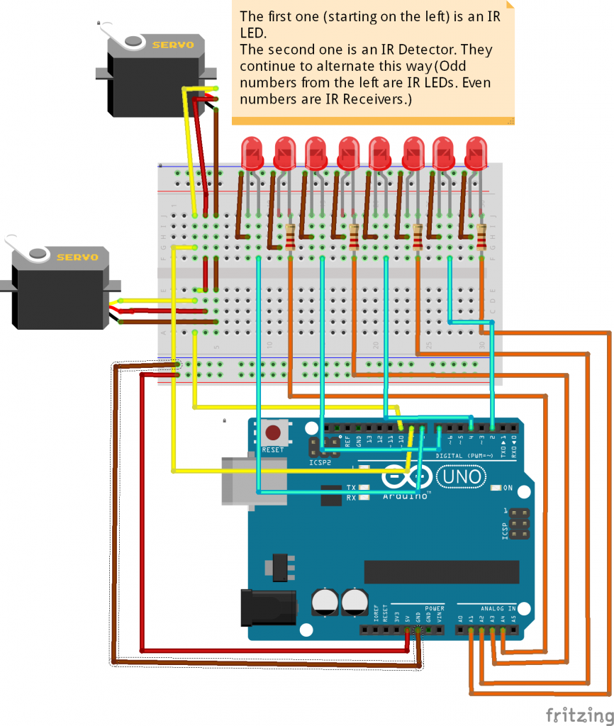
For this project, I was using two continuous servos, which are high powered motors that rotate based on degrees. For example, when the servo is in position 90 it’s not moving versus when it’s in position 180 its going forward and when it’s position 0 its going in reverse. For the sensors, I am using infrared LEDs and Infrared receivers. How the sensors work is that as the LEDs emit IR light the receiver being next to it will be able to detect the light after bouncing off the surface of the table.

One of the most challenging things I had to deal with is the electronic side of things. I could get the code down solidly but I kept having issues with the sensors as the value I was receiving kept going berserk. After countless attempts of changing the circuit to power the servos first then the sensors, I was still having issues. With the help of lead instructor Graham, we could figure out a solution by connecting a wire the vin pin on the Arduino and connecting it directly to the servos. This allows the voltage to go directly to the servos without going through a voltage regulator.

My time here at BlueStamp Engineering has allowed me to understand whether I want to pursue engineering in the future; however, I still do not know what routes in engineering I want to take but my mind is leaning towards mechanical and electrical engineering. Having this opportunity really allowed me to get a hands-on experience in engineering and what it has to offer.

Final Project

My second milestone consisted of building the chassis and mounting the finished circuit. The robots and wheels are made from acrylic. One of the issues I had to deal with was the laser cut files and how they were larger than the piece of acrylic we had, so the person who had it laser had to estimate the size needed. When the laser cut acrylic arrived, the body of the chassis was complete, however, the wheels couldn’t be laser cut due to an error in the file, so I had to drill and mill the wheels out. Using these tools was very fun. Upon finishing the assembly, I ran into another issue which was that I was missing a wheel to be able to turn my robot. My instructor and I engineered a solution by using a Pololu ball and creating a mount for it. One of the most problematic things I had to deal with was when plugging in both servos it would interfere with the signals from the IR sensors this was because it would create a voltage drop causing the values I was receiving to go berserk. After countless trouble shoots, I got everything to work by connecting a wire into the vin pin on the Arduino and connecting it to power on the servos to get their own source of current before being changed into 5 volts it finally worked. Now that the chassis is complete, my next goal is to finish the coding. Since this is my first time coding it’s difficult to get the robot to reverse and turn when the IR sensors are getting a specific value and now that I have part of it working where the front servos stop when the value it’s supposed to receive isn’t accurate. My next goal is to give the tabletop wandering robot more functionality.

First Milestone

My first milestone was completing part of the circuit that will be on my robot. This involved learning how to connect servos, IR LED’s, and IR receivers to an Arduino, which is the micro controller I am using and programming on. Having no prior knowledge in programming made it very difficult to work with the infrared LED’s and infrared receivers. Before working with the sensor, I started by programming the servos to understand how they functioned. When connecting the servos to the Arduino board, I learned that they need to be connected to a PWM pin. After accomplishing to get the servos to rotate, my next step was to get my IR sensor to work, so I separated the task and worked with the IR LED’s followed by the IR receivers. The IR LED’s need to be connected to a digital pin and the IR receivers to an analog pin. When working with the IR LED’s, I had trouble seeing if they worked when using my phone since most smartphones can detect IR light, but I later found out that iPhone’s cannot detect infrared. After checking that the LED’s worked, my next goal was to get the receivers to work and get a constant reading from detecting IR light. The value received is measured in voltage but in 8-bit readings which are scaled from 0-1023. After getting a constant reading on the serial monitor, my following goal was to get a servo to rotate when there is a value less than 1000, which means the IR receiver is detecting IR light, and stopping the rotation when the value is greater than 1000, which the IR receiver is not detecting IR light. The distance between the IR LED and IR receiver affects the value received. Now that I got one servo to move when the constraint is true, I will be working on adding more sensors and connecting more servos. My next milestone will be to build the chassis including the circuitry.

Starter Project

For my starter project, I chose the MintyBoost, a portable battery powered usb charger. The MintyBoost converts 3V to 5V using a boost converter circuit. Before assembly, I looked at the parts necessary to build the MintyBoost. Then, I looked at the schematic, I was confused about how to read it and understand it. Additionally, I was confused of the names of the parts and the purpose they serve in the board. Coming into this program, I have no knowledge of any circuitry. I had noticed that there were many resistors and the purpose of resistors is that they control the current that goes throughout the circuit. Without resistors, there would be infinite current causing the circuit to overload. As I was finishing my project, I was slowly able to understand how it works and the usefulness during the building process. Once I finished soldering the diodes, resistors, and capacitors onto the board and attached the power supply, I tested the voltage before attaching the usb female jack and I got a specific read not greater than 5.2 and no less than 4.8. Afterwards, I attached the usb female jack and connected my phone to test if it worked and it did.

Leave a Comment

Start typing and press Enter to search

Bluestamp Engineering