Alexa for Home Automation
My name is Ranesh and my main project is Alexa for Home Automation. For my first few weeks here, I explored the web communication between Alexa and Particle, and the microprocessor used to control the components. I experimented by making Alexa turn on and off the LED lights and get temperature and humidity readings from the DHT22 temperature sensor. For my modification, I made an electricity budget system. This system monitors how much budget an electrical device has expended and if the devices crosses the budget, it is shut off. The users have the option of asking for status from Alexa or receive notifications on their phones. Additionally, the users can view previous budget analytics as graphs and predict the time duration for a given budget amount on an app.


Engineer
Ranesh
Area of Interest
Electrical Engineering and Computer Science
School
Cupertino High School
Grade
Rising Senior
Final Milestone
Goal
For my final milestone, I made the electricity budget system more user friendly that gives them more autonomy in analyzing the results of their electricity budget. I first added a notification system that lets the users know when they have crossed half of their electricity budget, three-fourths of their budget, and when their devices have been shut off once their devices completely cross the electricity budget. This project is also accompanied by an Android app that lets the users view their past three budget runs in three different graphs and also lets them predict the duration their device can run given a budget based on past data. Finally, I soldered all the connections to the PCB Board to make this project into a finalized product.
Coding Particle
I explored three different ways of sending notifications to the users. First, I considered using IFTTT (if this then that), a software that connects different services, such as Facebook with messaging, etc, to send the notification. Although it was easy to set up the IFTTT applet since there was no coding required and I could directly track the Particle variable and send it as a SMS through their own platform, the applet said that it ran only once in one hour. Upon further research, I figured out that IFTTT has only updated some services to run frequently. After that, I looked into using AWS SNS to send an email notification. However, when I implemented that feature by sending data over a web hook, the only response I was getting back from AWS was an internal error. Finally, I used a program called Pushbullet. This app has been used by developers before, which is why it seemed like a viable alternative. Therefore, I created a web hook in JSON for sending a notification, which basically pushed the value to the POST method of the Pushbullet API by getting the value from the Particle code. In the Particle code, I checked whether the totalEnergyValue variable crossed half of the budget, 75% of it, or when it crossed the budget overall. Since this was checked in the main loop, I had to make sure that the notifications of the same thing weren’t sent repeatedly. That is why I had to check whether the notification of, say 50%, was already sent. Therefore, I used a boolean variable to check for the first time whether the notification was sent. Once the notification was sent, I changed the state of the boolean variable so that the notification wouldn’t be sent again. I was also able to send the data every two seconds to Firebase Database, a service owned by Google, by creating another web hook. In each push command, I sent the totalEnergyValue variable, the index of iteration, and the date.
Coding Android Java Files
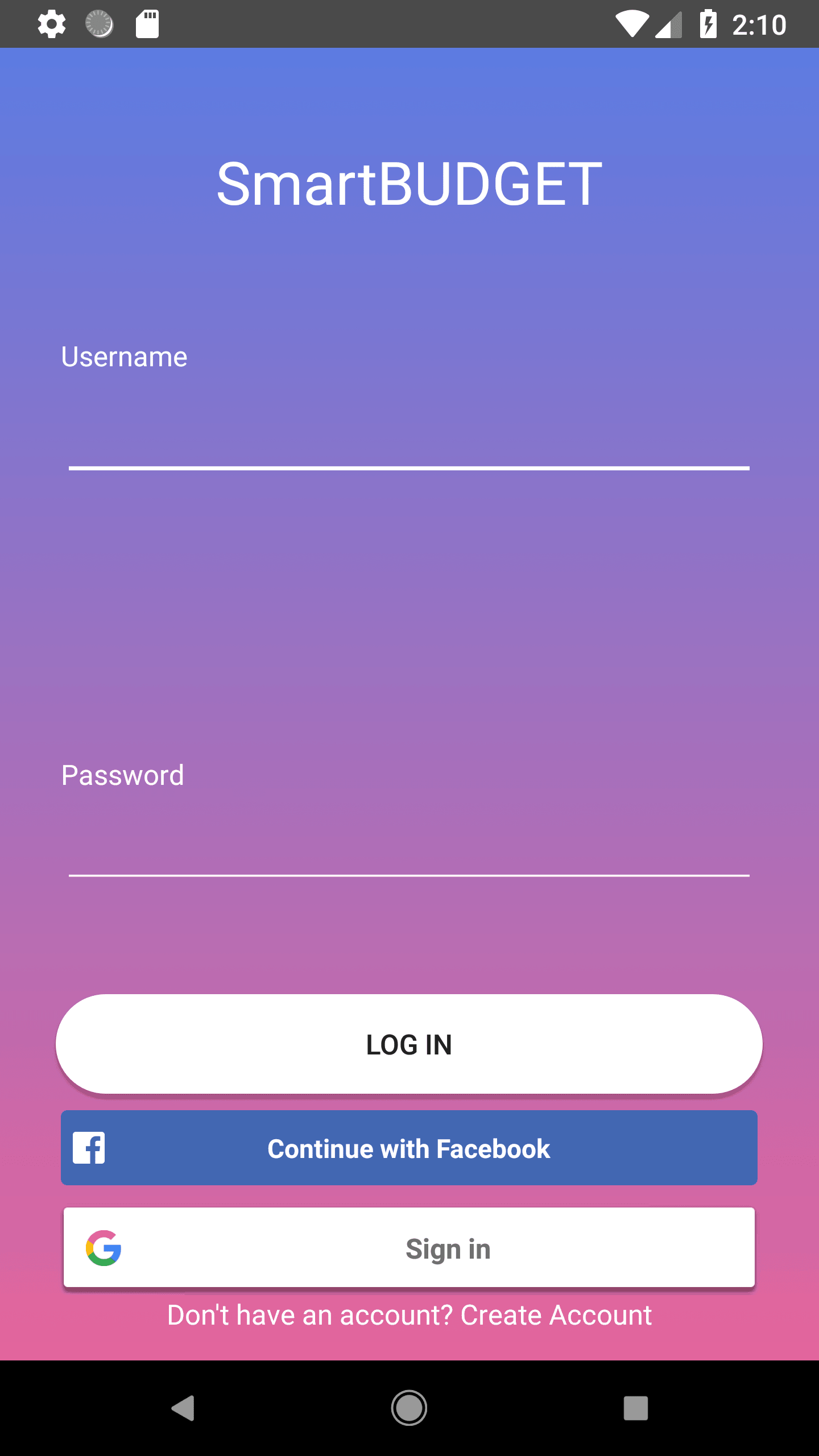
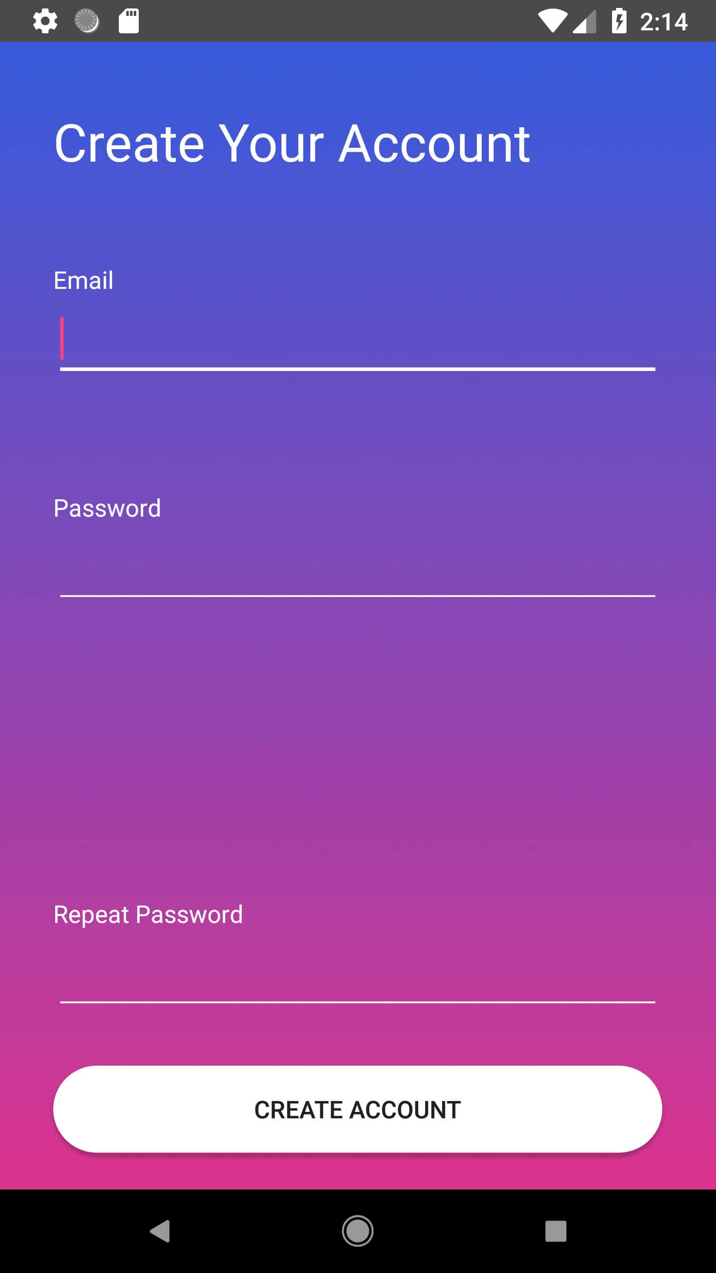
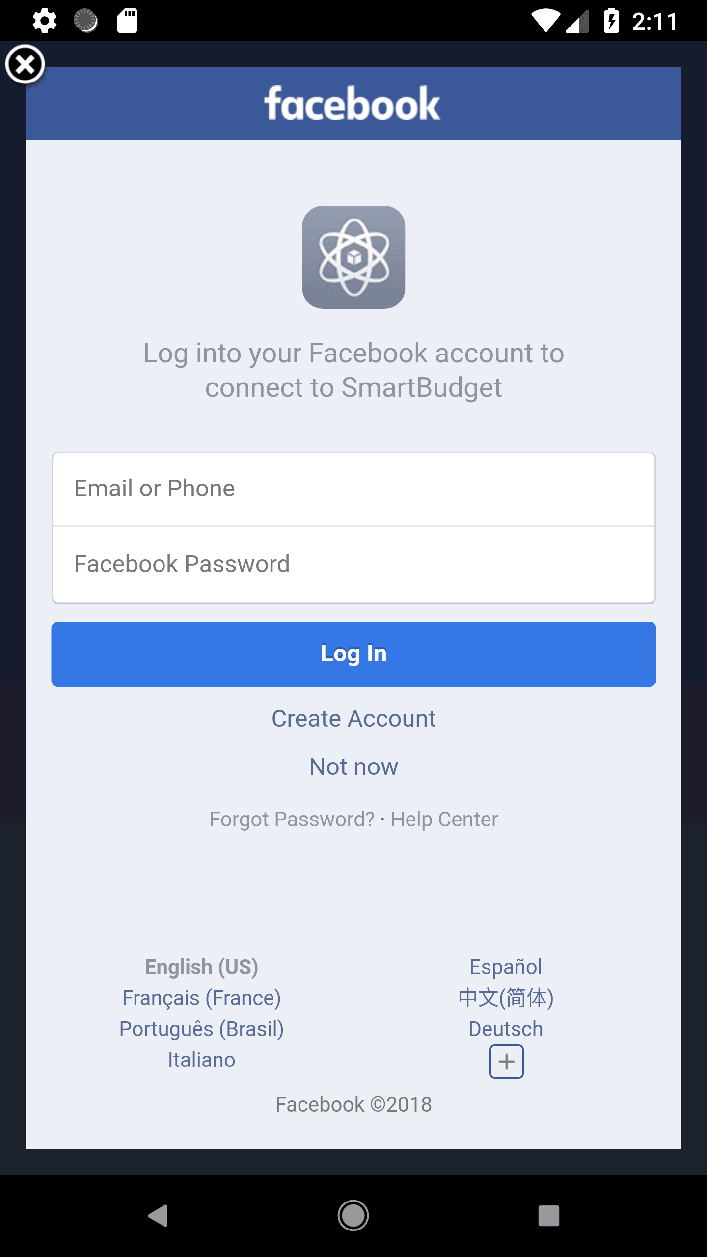
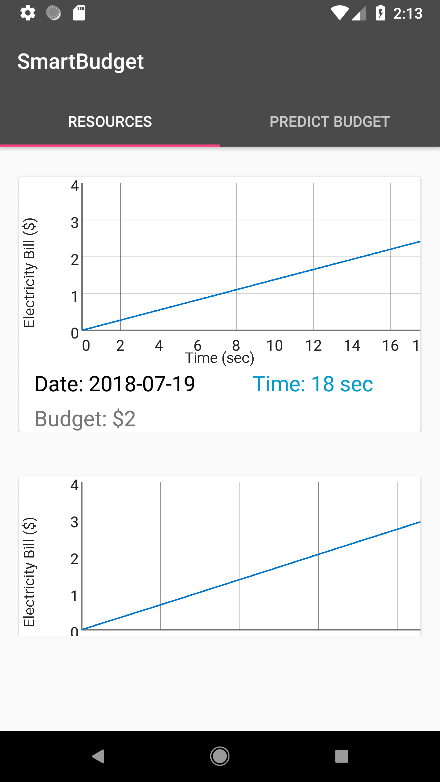
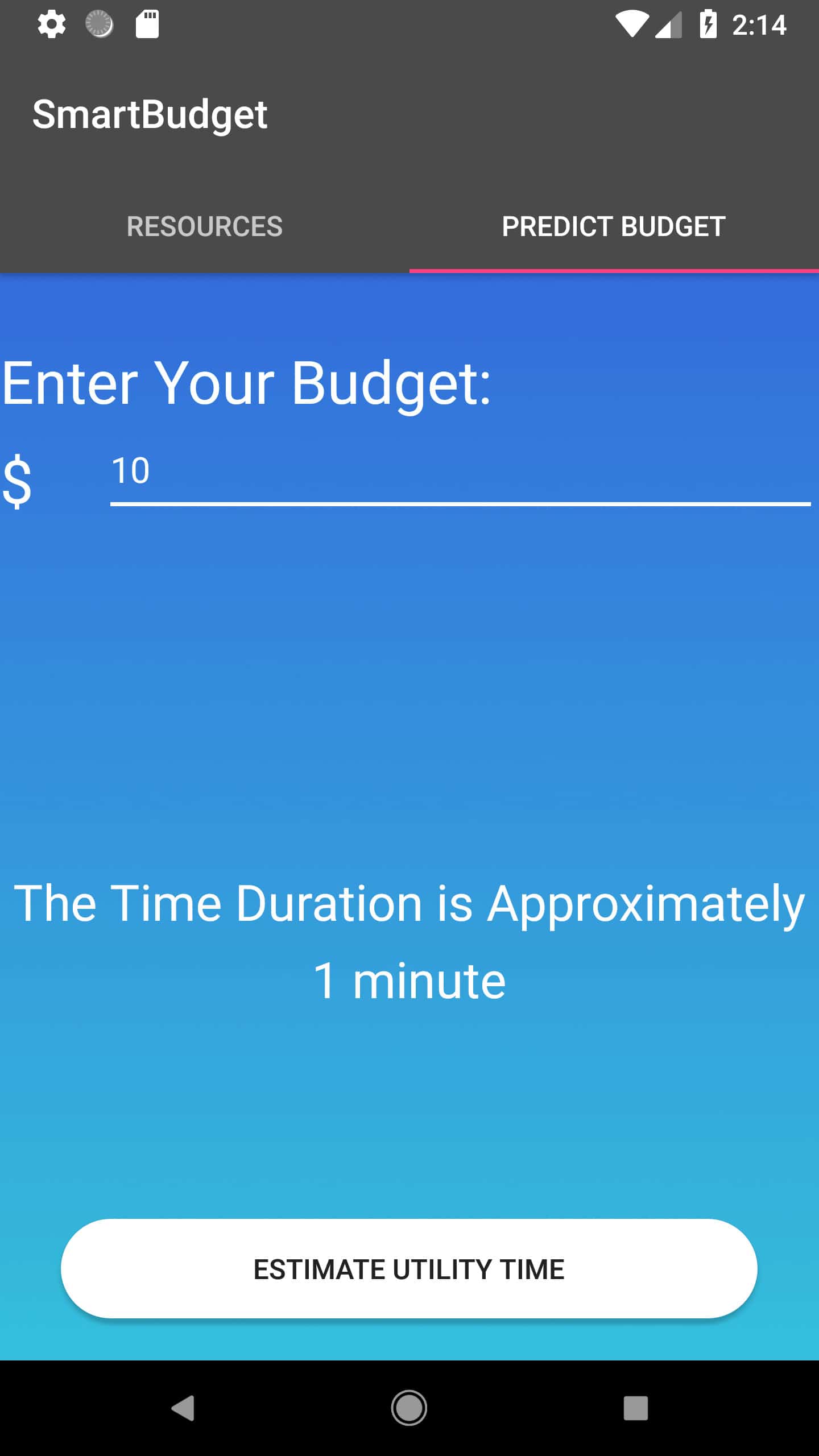
Overall, the process flow of my app was the login screen with email, Google, and Facebook authentication, create account page, the graphs of previous runs, and a “Predict Time” page given a budget. Setting up the authentication was the easy part. However, when I was extracting the data from Firebase to create the graphs, some of the graphs were being duplicated. After multiple runs, I still could not locate the error but I noticed a pattern: after five graphs the data was repeating. Therefore, to make sense, I created a feature of showing the latest three runs of the system. The way the data was extrapolated was that while looping through the database, I kept adding the energy values to an Arraylist. Once the energy again came to zero, I made an Arraylist of custom objects (I coded the class for this object) that also took the date and the total budget set. This object was added to the Arraylist of its own type and at the end of the loop, the Arraylist is set to the Adapter for the list, which is then set to the RecyclerView object, which is basically a fancy list with each item being a customizable Card. When the adapter was set, each item from the Arraylist, one by one, was sent over to another class that populated the elements of each card. This included the graph by iterating through each ArrayList of electricity budget per object, the date, and the total budget. I also created a predict budget option. The way this worked is that when the user entered a budget, the program went through the database and it calculated the slope of time over budget of the latest run (since the graph was always linear) and that amount was multiplied by the slope to get a predicted time either in minutes or seconds, converted accordingly.
Coding Android UI
Unlike my prior apps before Bluestamp, I focused a lot on the user interface so that the app doesn’t only have complex functionalities but it is also appealing to the user so that the app is used in the first place. Therefore, I followed the material design conventions that professional Android developers have traditionally used. Few key components of this convention are sharp color contrast, different layers of widgets (such as buttons casting a shadow), even spacing, proper usage of the screen, and keeping as few widget on the screen as possible while performing the desired functionalities. In order to achieve this, I first focused on the background colors. I wanted to have a blue base, but at the same time include subtle changes in color, hence the shifting colors in the main log in screen and fading colors in create account and predict time screens. Next, I wanted to focus on the proper usage of space, which is why most of my widgets occupy most of the screen and each type of widget is placed close to each other, such as all the edit text fields near each other and all the log in option in the main screens closer to each other. As far as contrasting colors go, I created light black tabs with white background for the graphs. I also set the elevation levels for buttons and the card views containing the graphs to make them more noticeable to the users. I also included some subtle stylistic elements, such as round edges for the buttons, to enhance the user experience. Having a clean and professional user interface not only helps the users in navigating through the app but it also gives the developer credibility of creating reliable products.
Bluestamp Experience
Overall, my experience at Bluestamp has been wonderful. Before coming to Bluestamp, I knew Android App development and Java. However, the flexibility of the program allowed me to explore difference programming languages, such as Node.js, JSON, and C++/Arduino. More importantly, however, I got to learn the different applications of programming. From making apps to making a whole IoT system that controls and analyses the performance of hardware components, I feel that I have enabled myself to fully realize and utilize the untapped potential of programming. IT wasn’t only the technical knowledge that I gained. Through the milestone videos and demo night presentation, I have become a more confident communicator than I previously was while at the same time having fun hanging out with my peers and instructors from all over the country. The combination of soft and technical skills I learned here has shaped me into a more experienced engineer who is ready to take on new challenges.
SmartBudget App
Third Milestone
Goal
For my third milestone, I decided to modify my base project by making a home budget system using Alexa. Essentially, a user can tell Alexa to turn on or off a device (in this case a fan) and the user can set a electricity budget via Alexa. Next, the users can ask Alexa to give the status of their electricity consumption as compared with the budget set, which is reported in percentage. Finally, when the electricity consumption crosses the budget set, the device is automatically turned off, thus saving the users’ their electricity costs.
Setting up Alexa Skill Set
To accomodate the new changes, I first had to set up new statements and slots that Alexa would detect and take values from respectively. I created four new slots for this functionality: statusSlot, dollars, cents, and devices. The statusSlot would detect the request of the users asking for the percentage of the electricity consumption, the dollars and cents slots would take the budget value in dollars and cents, and the devices value would handle the specific requests for turning on or off a specific device. For this last command, I used the onoff slot previously created to handle the user’s request of turning a particular device on or off. For the statements themselves that Alexa would recognize, I had to code multiple variations for the budget input in order to account for dollar vs dollars and cent vs cents when the user said “one” for either of those values and in order to detect when the user just said dollars, cents, or gave both values.
Coding AWS Lambda
My main changes regarding the AWS lambda was accounting for the appropriate data extraction from each slot value and sending them to the Particle API. First, I handled the status value; when the user says “electricity” and “status” afterwards”, the path to the Particle API is directed to “getEletricity” method (tagged by using “getElec” in the path name). Then, it checks for two values that are returned from the Particle API. If the JSON return value is zero, then the budget was not set in the first place, and the user is prompted to do so. If a certain value is returned, then that value is the percent value and Alexa then tells the appropriate message using that value. Next, I check for the device by using the “devices” slot. Although I am just using a fan, I also account for the light since I will be implementing that next. As of now, when the user says the command with fan as a slot value, then the pin to which the fan is connected, D3, is set as the pin value. Then the program goes to check whether the pin value is populated. If it is, then it checks the “onoff” slot and depending on whether the user said “on” or “off”, the state of the pin is either set to “HIGH” or “LOW”. When the pin value is checked to by “D3”, then both the pin and the pin value are sent to the Particle API in the same way as with LED lights in milestone #1. Finally, I took the budget amount as dollars and cents. For this, however, I did not use if-else statements but just two if statements since the user could send a combination of both the values. The program then checked whether a monetary amount was entered by checking a boolean variable checkBudgetValue which was set to true while checking if either the dollar or the cent variables were not null. The cent value was concatenated to the dollar value and a decimal point after the dollar value and then sent over to the Particle API.
Coding Particle IDE
In the Particle IDE, I created three key methods: getElectricityStatus, setBudget, and turnOnOff, and they do what they exactly sound like. For the setBudget function, I essentially set the global variable BUDGET to whatever budget was passed in, and the loop function basically checked to see whether the total energy consumption was over the Budget. If so, then the fan was turned off by setting the D3 pin to LOW. That way, the relay switch, which controls the circuit connection to the fan, breaks the connection. The total energy consumption was calculated by multiplying the current, voltage, the delay interval (two seconds), the conversion factor from seconds to hours, and the conversion factor from milli Amperes to Amperes. I did not calculate kilowatts-hour but just watts-hour because to reach a set kilowatt-hour amount would take a long time, which is not suitable for the demonstration purposes. I then converted that amount to a cost by multiplying thirteen cents, the cost per kilowatt-hour in California but in this case used for watt-hour. For the getElectricityStatus, the method returned the percent by dividing total Energy Value tallied with the total budget set. And finally, for turnOnOff method, I decoded the pin from the state from a single string parameter, which was then used to set the appropriate pin to either HIGH or LOW based on the appropriate state.
Circuiting
I had to change my previous circuit drastically to accomodate the new loads. For example, I had to set a whole new potential reference for the computer fan to work since the 3.3 V from Particle would not be enough to power the fan. To do so, I connected the Anker (a battery pack) with a breakout board. The VCC and Ground terminals were then hooked up to the positive and negative terminals of the breadboard. Then, I hooked up the fan’s positive terminal to the breadboard’s and the fan was then connected to the current sensor. The other end of the current sensor was connected to the relay switch’s COMMON pin. The NO (normally open) slot from the relay switch was connected to the 9 V potential from Anker and the VCC, GROUND, and COMMON pin from the current sensor was connected to the 3.3 V potential from the Photon, the ground, and the A0 pin which reads the current data coming in.
Second Milestone
Goal
For my second milestone, I got the Alexa to tell the user room temperature (measured in celsius) and humidity based on what the user asks it. For this, I used a DHT22 sensor that was connected to D2 pin of the particle. As far as the coding goes, the AWS Lambda essentially sends over the parameters to the specific method that it would expect value from (either temperature or humidity). The Particle API then uses the DHT library to carry out the function and then it returns the respective value, which Alexa tells user.
Setting up Alexa Skill Set
First of all, I defined two sample utterances for temperature/humidity sensors: “What is the temperature/humidity here” and just “Temperature/Humidity”. Having another simpler utterance option ensures that the user has more than one way to get the appropriate information out of Alexa. In my case, I had to use the second, simpler utterance so that Alexa did not mix up the slot (key) words with other “fluff” words.
Coding AWS Lambda
In AWS Lambda, the code essentially looks for if the user said either “temperature” or “humidity”. If that is the case, then depending on either temperature or humidity, the path of referring the return function from Particle IDE is set according to that method’s respective tag name (“gettmp” or “gethmd”). After, AWS Lambda bundles all those parameters and sends a JSON request to the Particle API. However, in this case, the Lambda expected a return value from JSON, which then made Alexa say an appropriate statement with that respective value.
Coding Particle IDE
In the Particle IDE, the DHT library was used to get the specific functions that would enable me to get values on temperature and humidity detected by the temperature sensor. Therefore, after setting the loop interval for 10 seconds (a long delay so that the readTempeature method has enough time to read the temperature), the readTemperature/Humidity were type casted to integer values and then stored in variables temperature and humidity. Finally, they were returned via the two getter functions (getTemperature and getHumidity).
Circuiting
The circuiting was modified a bit for the particle to accommodate the temperature sensor. First of all, the ground pin and the 3.3V pin were connected to negative (blue) and positive (red) side of the breadboard so that there were reference voltage grounds were created. Then, pin 1 of the temperature sensor was connected to the red side, pin 4 was connected to the blue side (to establish a voltage difference in the temperature sensor), and pin 3 was connected to pin D2 of the photon device with 10k ohm resistor connected in parallel to limit the current flow.
References
Please refer to the base project description here and the GitHub code here.
