3D Printed Robotic Arm
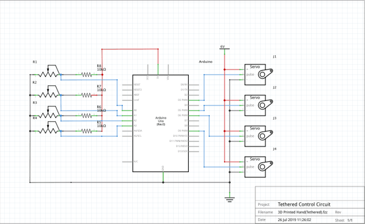
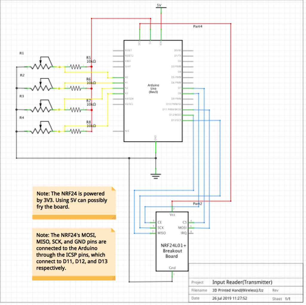
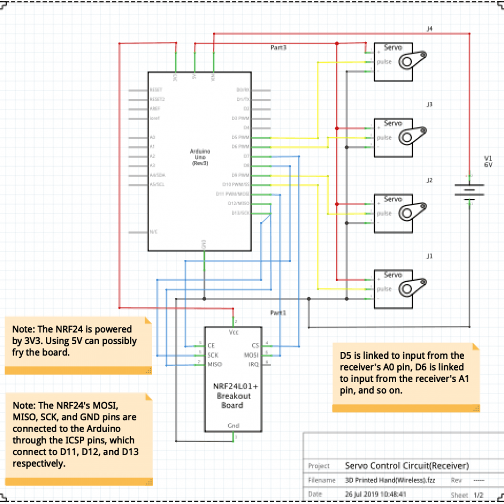
This is a 3D printed hand wirelessly controlled by a glove. The hand was assembled according to instructions on http://theroboarm.com/section1.html. I programmed one arduino to read input from the glove, and another to control the servo motors. Documentation is shown below.
Engineer
Qilin Y
Area of Interest
Computer Science
School
Abraham Lincoln HS
Grade
Rising Junior
Third Milestone
Watch my Demo Night presentation here!
#include <RF24.h>
#include <Servo.h>
#include <SPI.h>
const int numServos = 4;
const int measurementPins[] = {A0, A1, A2, A3}; // pins to connect to the flex sensors
const int resistanceRangeA[] = {530, 510, 575, 530};
const int resistanceRangeB[] = {770, 650, 740, 670};
int increment = 5; // rate at which to move the servos – increment° / 50 millis
const Servo servos[numServos]; // creates the array of servo controller objects
const int servoPins[] = {5, 6, 9, 10}; // pins to attach to the servos
// 5 : ring/pinky, 6: middle finger, 9: index finger, 10: thumb
int servoAngle[] = {0, 0, 0, 180}; // stores the current angle of the servos
int offsetAngle[] = {0, 0, 0, 180};//allows me to control the direction of the servos
const int cePin = 8; // chip enable
const int csnPin = 7; // chip select
RF24 radio(cePin, csnPin);
bool writePin = false; // whether the arduino is being used to write
const uint64_t pipeAddress = 0xF0F0F0F0F001; // commmon address between the two NRF24l01 boards
const int payloadSize = 8 * numServos; // 8 bits per sensor/servo
void setup() {
Serial.begin(9600);
radio.begin();
(writePin? setAsWriter() : setAsReader());
radio.setPALevel(RF24_PA_LOW);
}
void loop() {
if(writePin){ // if this is the transmitter
unsigned long output = 0; // variable that stores input
for(int i = 0; i < numServos; i ++){
long val = analogRead(measurementPins[i]); // read from a flex sensor
val = map(val, resistanceRangeA[i], resistanceRangeB[i], 0, 180) / (4 * increment); // maps raw output to servo rotation, rounded to reduce twitching
val *= 4 * increment;
val = abs(val – offsetAngle[i]);//flips servo rotation if offsetAngle[i] is 180
// makes sure val is in the correct range
if(val < 0) val = 0;
if(val > 180) val = 180;
output += (val << (i * 8)); // stores val in the last 8 bits, then the next 8 bits to the left, and so on.
}
bool sent = radio.write(&output, sizeof(output)); // send output
if(!sent)Serial.println(“message did not send”);
}else{
long startMillis = millis();
while(!radio.available()){
if(millis() – startMillis > 2000){
Serial.println(“message timed out”);
return;
}
}
unsigned long input = 0;
radio.read(&input, sizeof(input)); // records the message in the variable input
for(int i = 0; i < numServos; i ++){
int val = ((long)0xFF << i * 8 & input) >> i * 8; // gets last 8 bits, then the next 8 bits to the left, and so on.
// rotates the servo, and throttles speed
int count = 0;
if(val > servoAngle[i]) count = increment; // count is positive if val > servo’s current angle
if(val < servoAngle[i]) count = -increment; // count is negative if val < servo’s current angle
if(val == servoAngle)continue; // servo has reached the desired angle, continue to the next servo
servoAngle[i] += count;
servos[i].write(servoAngle[i]); // update servo angle
}
}
if(!radio.isChipConnected())Serial.println(“chip not connected”);
delay(50);
}
void setAsWriter(){
radio.openWritingPipe(pipeAddress);
radio.stopListening();
}
void setAsReader(){
radio.openReadingPipe(0, pipeAddress);
radio.startListening();
for(int i = 0; i < numServos; i ++){
servos[i].attach(servoPins[i]);
}
}
Second Milestone
#include <Servo.h>
const int numServos = 4;
const int measurementPins[] = {A0, A1, A2, A3}; // pins to connect to the flex sensors
const int resistanceRangeA[] = {530, 510, 575, 530};
const int resistanceRangeB[] = {770, 650, 740, 670};
int increment = 5; // rate at which to move the servos – increment° / 50 millis
const Servo servos[numServos]; // creates the array of servo controller objects
const int servoPins[] = {5, 6, 9, 10}; // pins to attach to the servos
// 5 : ring/pinky, 6: middle finger, 9: index finger, 10: thumb
int servoAngle[] = {0, 0, 0, 0}; // stores the current angle of the servos
int increment = 2; // rate at which to move the servos – increment° / 50 millis
void setup() {
Serial.begin(9600); // for debugging
for(int i = 0; i < numServos; i ++){ // attaches pins and rotates servos to 0° position
servos[i].attach(servoPins[i]);
servos[i].write(0);
}
}
void loop() {
for(int i = 0; i < numServos; i++){ // for each servo
int val = analogRead(measurementPins[i]); // read from a flex sensor
val = map(val, resistanceRangeA[i], resistanceRangeB[i], 0, 180) / (2 * increment); // maps raw output to servo rotation, rounded to reduce twitching
val *= 2 * increment;
// makes sure val is in the correct range
if(val < 0) val = 0;
if(val > 180) val = 180;
// rotates the servo, and throttles speed
int count = 0;
if(val > servoAngle[i]) count = increment; // count is positive if val > servo’s current angle
if(val < servoAngle[i]) count = -increment; // count is negative if val < servo’s current angle
if(val == servoAngle)continue; // servo has reached the desired angle, continue to the next iteration
servos[i].write(servoAngle[i] += count); // update servo angle and turns the servo
}
delay(50); // wait 50 milliseconds before checking the flex sensors again.
}