2018
Reflection
When I came to BlueStamp for the first time, I was scared. I was unsure of how I would finish my first actual project, yet I did it. This second year was more difficult as I only had three weeks, but I still finished it. I never realized until today how mature I became. With these qualities, I now see a glimpse of what I can accomplish under pressure. I appreciate this experience because it opened my eyes to better opportunities. This year, I learned how to write better documentation for my website which was very useful. I also learned how to become even more independent compared to last year. Lastly, I learned how to handle strain better which will definitely help me in the future. These are just a few of the things that I learned along with so much more and I am happy about it.
Final Milestone

Even though I finished my project, there were still challenges, as there always are. This challenge, like the last, also included my motors. My motors were still too weak even after changing the material of my chassis. So I changed to the motor to be bigger and more powerful. This challenge also came with other challenges like my tires. The axle of the motor was too big for my tires to fit. So I glued the tires to the nuts which were then glued to the axle. At the time the wheels would break off, but it worked for the most part.

In total, my project included: three ultrasonic sensors, one Arduino, one breadboard, two batteries, two motors, two wheels, one dual h-bridge motor controller and a bunch of wires.
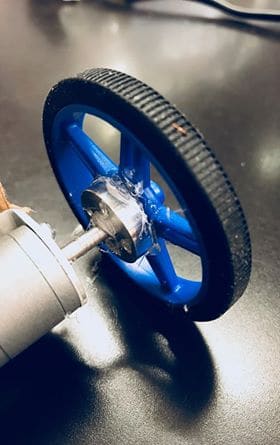
This experience has shown me that anything can happen at any time. This means you have to be prepared to fix it and move on. If I told my past self before this project that I could make it this far, he would say that I was crazy. This shows how far I have come and I cannot wait to go far. Blue Stamp has taught me that I wanted to go into mechanical engineering. The projects that I would prefer to do would be more robotics and I hope the experience prepares me for my future plans.
| 1 | Arduino | Amazon | Uno R3 | 1 | $17.49 | |
| 2 | Ultrasonic sensor | Amazon | HC-SR04 | 3 | $5.65 | |
| 3 | Ball Caster | Adafruit | 1200 | 1 | $4.95 | |
| 4 | Pololu Wheel 32×7mm Pair | Pololu | N/A | 1 | $4.98 | |
| 5 | 30:1 Micro Metal Gearmotors | Pololu | N/A | 2 | $18.95 | |
| 6 | L298 Dual H-Bridge DC Motor Controller | Robotshop | RB-Ite-141 | 1 | $7.88 | |
| 7 | Battries | Google Express | N/A | 1 | $4.99 |
#define trigPin1 2
#define echoPin1 3
#define trigPin2 4
#define echoPin2 5
#define trigPin3 6
#define echoPin3 7

int dir1PinA = 12;
int dir2PinA = 11;
int speedPinA = 13; // Needs to be a PWM pin to be able to control motor speed

// Motor 2
int dir1PinB = 10;
int dir2PinB = 9;
int speedPinB = 8; // Needs to be a PWM pin to be able to control motor speed

long duration, distance, RightSensor, BackSensor, FrontSensor, LeftSensor;

void setup()
{
Serial.begin (9600);
pinMode(trigPin1, OUTPUT);
pinMode(echoPin1, INPUT);
pinMode(trigPin2, OUTPUT);
pinMode(echoPin2, INPUT);
pinMode(trigPin3, OUTPUT);
pinMode(echoPin3, INPUT);

pinMode(dir1PinA, OUTPUT);
pinMode(dir2PinA, OUTPUT);
pinMode(speedPinA, OUTPUT);
pinMode(dir1PinB, OUTPUT);
pinMode(dir2PinB, OUTPUT);
pinMode(speedPinB, OUTPUT);
}

void loop() {

SonarSensor(trigPin1, echoPin1);
RightSensor = distance;
SonarSensor(trigPin2, echoPin2);
LeftSensor = distance;
SonarSensor(trigPin3, echoPin3);
FrontSensor = distance;

Serial.print(LeftSensor);
Serial.print(" - ");
Serial.print(FrontSensor);
Serial.print(" - ");
Serial.println(RightSensor);

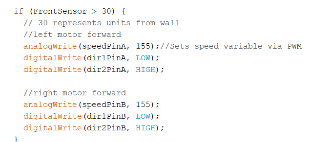
if (FrontSensor > 30) {
// 30 represents units from wall
//left motor forward
analogWrite(speedPinA, 155);//Sets speed variable via PWM
digitalWrite(dir1PinA, LOW);
digitalWrite(dir2PinA, HIGH);

//right motor forward
analogWrite(speedPinB, 155);
digitalWrite(dir1PinB, LOW);
digitalWrite(dir2PinB, HIGH);
}
else if (FrontSensor <= 60) {
analogWrite(speedPinA, 0);//Sets speed variable via PWM
digitalWrite(dir1PinA, LOW);
digitalWrite(dir2PinA, HIGH);

analogWrite(speedPinB, 0);
digitalWrite(dir1PinB, HIGH);
digitalWrite(dir2PinB, LOW);
if (LeftSensor > RightSensor) {
//only one motor runs here to turn
analogWrite(speedPinA, 155);//Sets speed variable via PWM
digitalWrite(dir1PinA, LOW);
digitalWrite(dir2PinA, HIGH);

if (FrontSensor > LeftSensor) {
analogWrite(speedPinA, 0);//Sets speed variable via PWM
digitalWrite(dir1PinA, LOW);
digitalWrite(dir2PinA, HIGH);

analogWrite(speedPinB, 0);
digitalWrite(dir1PinB, HIGH);
digitalWrite(dir2PinB, LOW);
}
}
else {
analogWrite(speedPinB, 155);//Sets speed variable via PWM
digitalWrite(dir1PinB, HIGH);
digitalWrite(dir2PinB, LOW);
if (FrontSensor > RightSensor) {
analogWrite(speedPinA, 0);//Sets speed variable via PWM
digitalWrite(dir1PinA, LOW);
digitalWrite(dir2PinA, HIGH);

analogWrite(speedPinB, 0);
digitalWrite(dir1PinB, LOW);
digitalWrite(dir2PinB, HIGH);
}
}
}
}
void SonarSensor(int trigPin, int echoPin) {
digitalWrite(trigPin, LOW);
delayMicroseconds(2000);
digitalWrite(trigPin, HIGH);
delayMicroseconds(10000);
digitalWrite(trigPin, LOW);
duration = pulseIn(echoPin, HIGH);
distance = (duration / 2) / 29.1;

}
Second Milestone
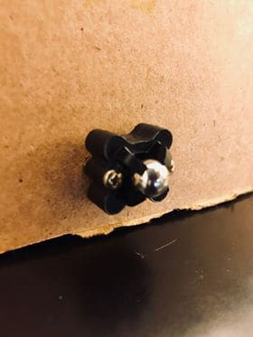
This milestone involved a huge problem because I did not initially intend to use cardboard. I was actually intending on using 3d printed parts for my project. The application I used to create these part was called Autodesk Inventor. The process was pretty easy and after I was all done designing my parts, I sent them to the 3d-printer. I faced a complication where my motors were struggling to move. The weight of my robot was to heavy so I had to replace my 3d-printed parts with cardboard.
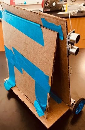
To do this, I snipped out another piece of cardboard and hot glued that to the bottom of my robot. This would be where I apply my ball caster to help my robot move and rotate smoothly. See link to ball caster here. I also applied cardboard behind my robot to tape for structural support, because my it started wobbling.
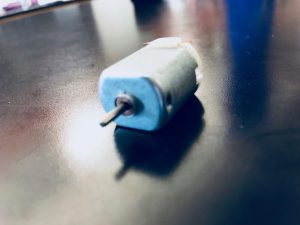
Time became a major variable throughout this milestone, but this time limit forced me to grow into a fast thinker. Now I can manage my time well compared to before when I came to Blue Stamp. As I had 3 weeks to complete my project I also developed a skill of rapid prototyping. With this skill, problems and solution come and go every day. What I can accomplish with this skill is unimaginable. I am satisfied with my project so far and cannot wait to see what I can accomplish during the time I have.
First Milestone

Now I am able to have my motors move in the same direction. I can also change which motor works and which does not in order to control which way the robot turns. At this point, this is all theoretical until I can see it in action. I used three ultrasonic sensors to detect distance. The ultrasonic sensor has two parts to it: the trig and the echo. The trig part of the ultrasonic sensor produces or triggers the sonic ping. The ping is then collected by the echo part of the ultrasonic sensor to name the distance. The logic is based on how close each ultrasonic sensor is to the wall. See link to the Ultrasonic Sensor here
The motors are controlled by a Dual H-Bridge Motor Controller and provide ease to code for the motors. It uses a power source like a battery or an Arduino to control the motors. The Motor Controller allows me to rotate the axle of the motors forward, backward, or not at all. This device also control the speed of the motors. See link to the Motor Controller here.


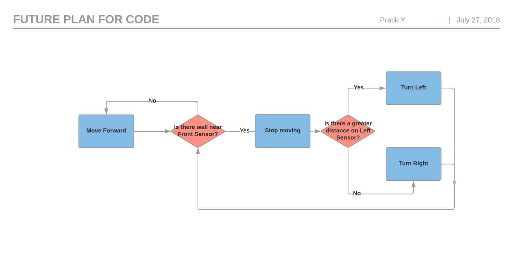
My code uses if and else statements for the ultrasonic sensors to detect the furthest distance. The plan is that if the ultrasound sensors are far from the walls, my hypothetical robot should move forward, but if the forward ultrasonic sensor is not going near a wall, the robot should react by choosing which turn to take. To figure this out, the ultrasonic sensors on the side detect their distance. Whichever sensor has the farther distance, the robot turns in that direction. For example, if the left ultrasonic sensor senses a distance of forty units, while the right ultrasonic sensor senses a distance of 50, the robot should turn right.
My biggest challenge throughout my first milestone was the coding process. After I set up my circuit for my Ultrasonic Bot, I did not know where to go next. I brainstormed at home to figure out where to start with my code. After brainstorming, I came up with the code to start working on at Blue Stamp. During the day, I tested the code that has the motor run and it almost worked. The motors were responding to my ultrasonic sensor but not correctly as one motor was running while to other motor was fidgeting around. After many test runs, my motors started working properly. One reason it started working could be because my I included a function to stop one of the motors instead of not specifying its state.

At this point, I finished my first milestone. Before I started this project, I did not think I would make it this far in basically a week. Last year, I went to Bluestamp, an Engineering Camp for Kids, for six weeks and I remember it took me a long time to get to my first milestone. So I feel amazing knowing that I finished my first milestone.
Starter Project
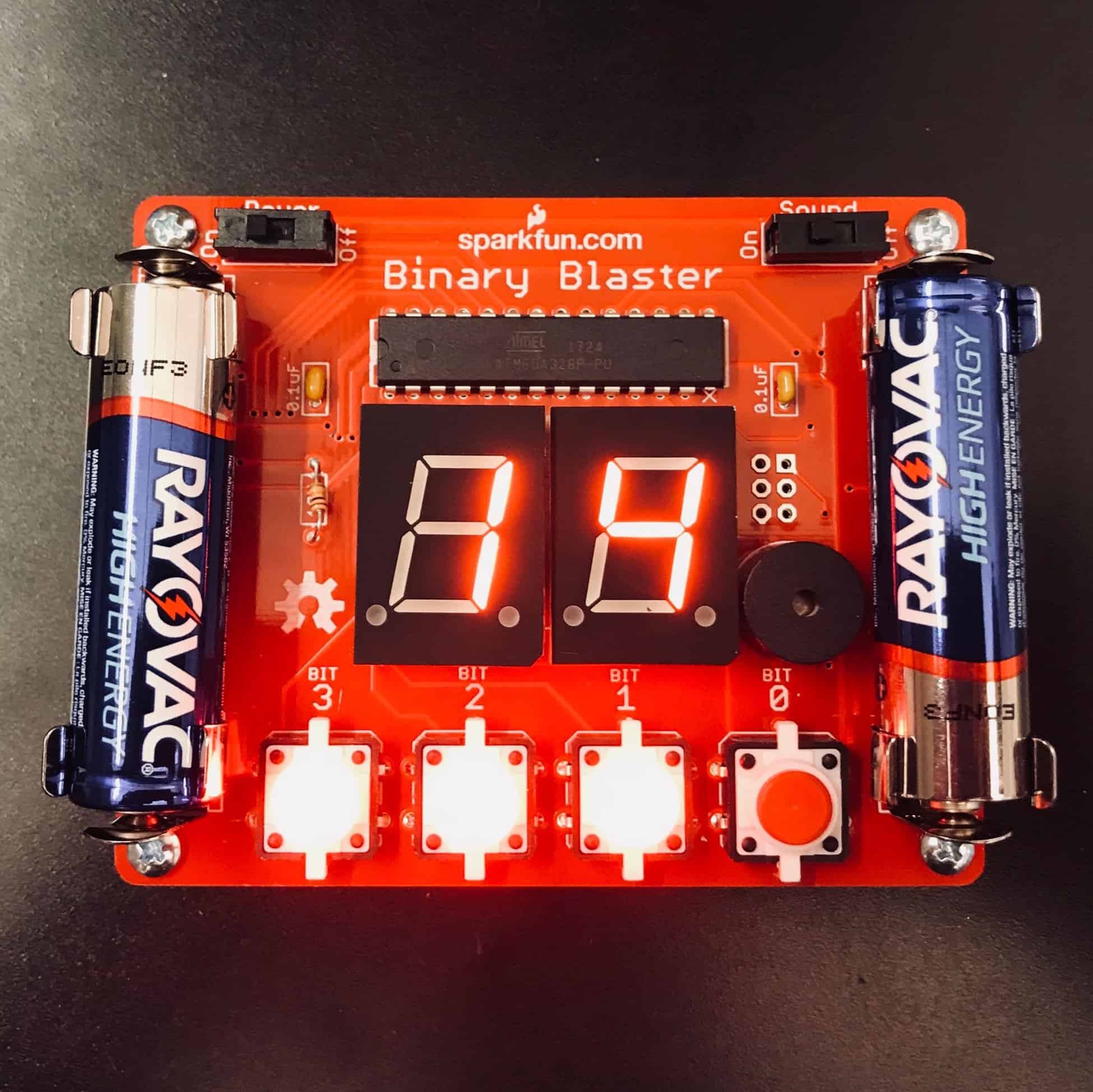
How it works is that you are supposed to convert numbers one to fifteen displayed in decimal to binary form. Figure 1: The fully assembled Binary Blaster can be seen above emitting digits by LEDs which is also represented as the LEDs in the button, converting decimal form to binary form. Anything above fifteen requires five buttons because there are more than four digits in a binary sequence. These digits are represented by bits which are the buttons shown in the picture. Binary uses a system where the highest digit is one. This is opposed to the decimal system where the highest digit is nine. Every number that has a base of two like one, two, four, eight, sixteen… increases the number of bits by one like this:
One = 1
Two = 10
Four = 100
Eight = 1000
Sixteen = 10000
Notice how each bit corresponds to the power of the decimal versions’ power. To play the game, watch as a number displays on the LED. The user presses the combination of buttons that represent the binary version of that value. For example, fifteen would be 1111 so you would click all the buttons. Ten would be 1010 so you should click the three-bit button and the one-bit button. The Binary Blaster utilizes a small circuit board with the following: two switches, two capacitors, one resistor, four buttons, one speaker, four battery holders, and two LEDs. Capacitors store electrical voltage. Resistors control the energy flow around the circuit. LEDs or light emitting diodes emit light. A diode allows current to flow only one way. Switches allow for electricity to travel around the circuit board. These components were soldered to the circuit board. There were not many problems that slowed down my progress, but, one problem that occurred was that my batteries had lost their charge. In the end, I switched the batteries out with new batteries and everything came together. For the most part, it was fun and easy to assemble at STEM Classes For Kids in New York.
2017
Final Milestone
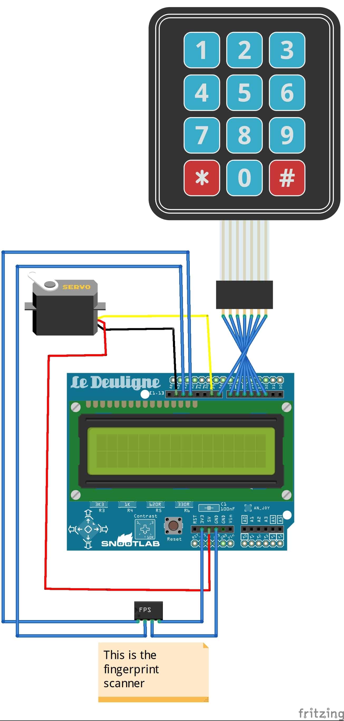
My Circiut
Reflection
Throughout my journey at Blue Stamp, I have learned a lot. First, I learned how to code and how to use power tools which I have never used before. I also learned some lessons like to not get frustrated from small errors and issues and to keep trying. I also learned have fun is the best way to motivate yourself to do more. This was a very fun experience I would definitely come next year.


