
Vision Recognition: Self-Aware Car | Ajmain Naqib
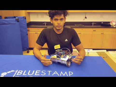
Hi, my name is Ajmain Naqib, and I am rising senior at Newtown High school. For my starter project, I put together a voice changer from the Velleman-kit’s MK171 voice changer kit and my advanced project is to build a self-aware car. It would behave accordingly to traffic lights and park itself when parking is found. I will be using vision recognition for this which is a completely new area for me.
My major involvement in engineering was in my school’s robotics team although I had the passion for engineering even since my childhood. In my school’s robotics team I am the captain, giving me the responsibility of overseeing the overall progress of build season’s mechanical, electrical, programming, media and business part, I am personally responsible for the mechanical and designing aspect of the robot. Other than being involved in the robotics team, personally I have worked with Arduino and Raspberry Pi to make several projects on my own.
Programming isn’t my area of expertise but I have always been keen to learn more. I have taken steps towards it. I know C, C++, HTML and somewhat Java. BlueStamp engineering gave me the extra push to learn more and get in-depth with Java. For my project, I need to write code in Java with OpenCV library for vision recognition, which has very little to no documentation. Being able to complete the tasks that was crucial for the project was a huge learning curve for me.
Final Milestone:
(Note preview is failing. Visit here for the video demonstration.)
Second Milestone
My second milestone was to get the vision recognition working. I used OpenCV library for this process and used Java. OpenCV is a library of programming functions mainly aimed at real-time computer vision. OpenCV is initially written in C++. There are a lot of documentation for python as well. But there is very few documentation in Java which was a great issue for me. The source code is attached to the bottom.

Fig 1
In order for me to process the image for my robot to act accordingly, first I had to code to find a specific color. After looking at many C++ and python code I kind of got the basic understanding. My first idea was to take a video feed, process it and draw a rectangle over the target and then find the center of the target. But a video is just composition of multiple frames. So instead of taking a video, the more efficient method would be to take a picture from the webcam.(Fig 1) The contents of the captured image had to be stored in “Mat”. Mat represents an n-dimensional dense numerical single-channel or multi-channel array. For debugging purposes, I had every change to be stored on a different mat.

Fig 2
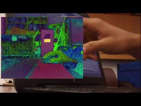
After taking the image for efficiency, it was converted to HSV. HSV stands for Hue-
Saturation-Vibrance. A range of HSV with upper and lower limit was defined to find the color. This is where I got stuck for a while. Playing with the numbers to the exact color is hard which exactly what I did after I got a basic idea of the color from the HSV color circle diagram.
So the steps I took later to make my life easier was to make sliders for every threshold

Fig 3
(Lower HSV and Upper HSV). It would change and show the change real-time which made finding the threshold for a specific color a lot easier.(Fig 3)
Then this new thresholded image was used to find contours. Contour is an outline, especially one representing or bounding the shape or form of something. This was done in order to use a function called boundingRect. It would find the object’s outlines and draw a rectangle over it. Next, it was easy to get the points of each corner and use Algebra to find its center and then calculate the difference from the center of the image. (Fig 4)

Fig 4
This process uses the FindCenter.java class. A problem that I noticed while doing this was in a video feed was that the rectangles I was drawing were overlapping. For that, I turned to just taking one image and showing the changes. But later I discovered it was because of line 127
List<MatOfPoint> contours = new ArrayList<MatOfPoint>();
had to be inside the loop. This is where the contours were being stored, and every time I was finding the contours, they were just saving.
Source Code: Github
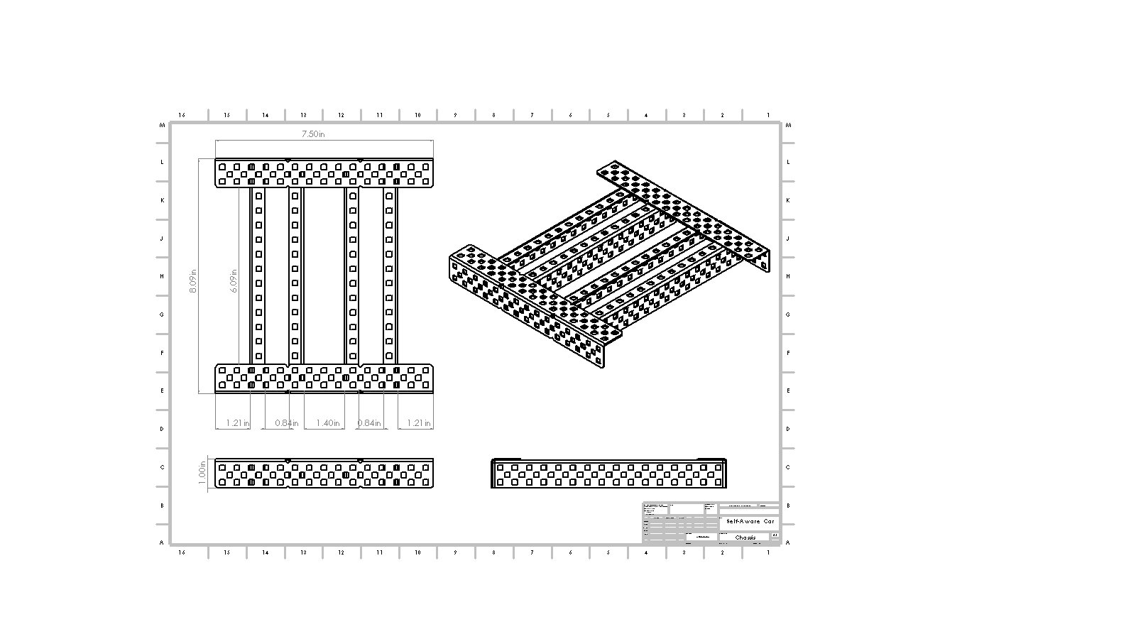
First Milestone

Mecanum Directional Drive
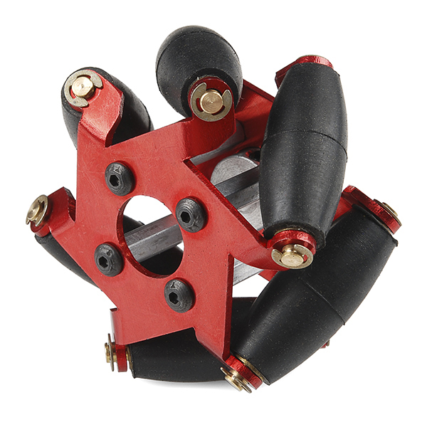
Mecanum Wheel
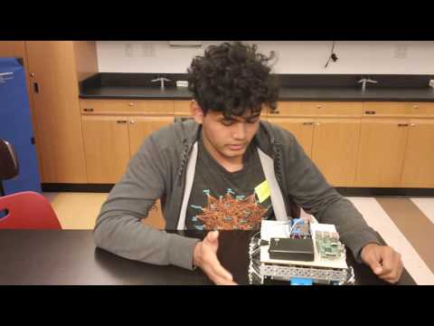
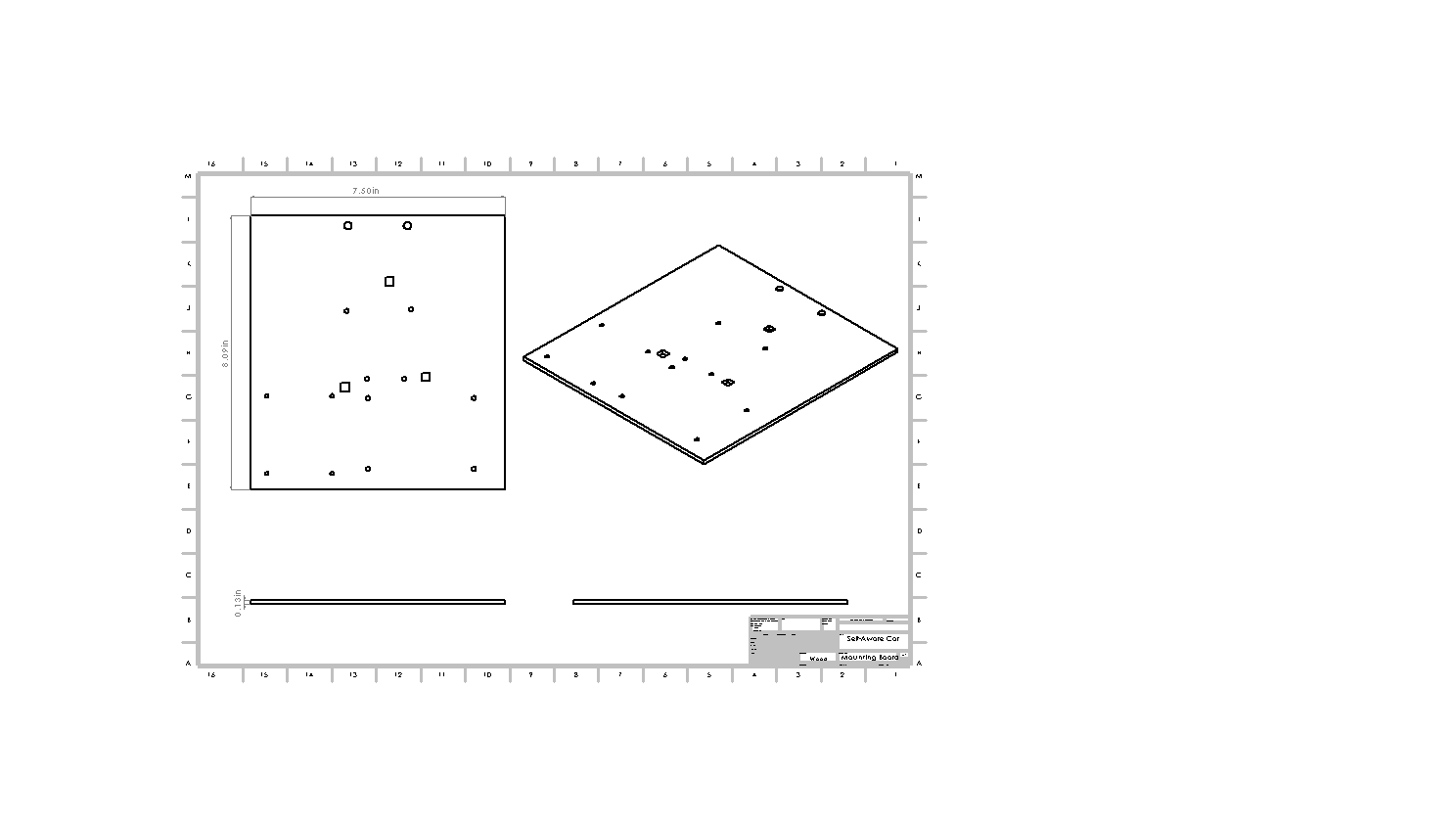
My advanced project is to build a self-aware car. It’s objective would be to identify road signs and behave appropriately alongside parking by itself using vision recognition and ultrasonic sensors when it’s complete. My first milestone was to make a mecanum wheel drive which would properly drive and avoid any obstacles.
The mecanum wheel is a conventional wheel with a series of rollers attached to its
circumference at 45 degrees to the plane of the wheel, parallel to the axis of rotation. By rotating different wheels in a different direction, the vehicle can be moved in different directions like forward, backward, left, right, diagonally.
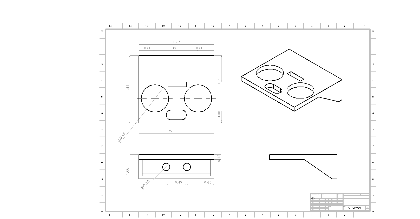
Also, I have an ultrasonic sensor attached to it which indicates the robot when to stop in order to avoid obstacles. How an ultrasonic sensor works is that it converts ultrasound waves to electrical signals or vice versa. The trigger pin emits a wave and echo pin receives it. With the distance formula using the speed of sound and the time it can be calculated how far the object is for an obstacle. I made a mount for the sensor.
One issue that I had was the wheel hubs since the metal ones weren’t in stock, we printed a substitute for it, but they are pretty weak, which prevents me from going left or right for now also some of my printed and cut models need to be redesigned. My next step would be to have the vision recognition to get to read to identify targets and communicate with the Arduino.
Starter Project
For my starter project, I put together a voice changer from the Velleman-kit’s MK171 voice changer kit.

Velleman MK171 Voice Changer
One important component of this project is it’s ICs, integrated circuit, which is a set of electronic circuits on a small plate, which is made out of semiconductor materials. This makes a circuit much smaller. In this project, I used 2 ICs-HT8950 voice modulator and LM386 amplifier. HT8950 is the component which has several steps to shift frequencies to make an input from a microphone have a dramatic change in the output such as robot voice, high-low pitch, and vibrato. LM386 is a low voltage audio power amplifier. It takes the output from HT8950 and processes it and delivers it to the speaker, which is the final output mode.
I used a 9V battery to power the circuit. First the current goes through a switch to a capacitor which filters the excess noise. Capacitors serve multiple purposes from storing electric charge to filter out lower frequencies, or extracting a signal from DC. An indicator LED diode switches on, passing the current through a Zener-diode which is reverse biased. Zener-diodes are to regulate a constant amount of current until a certain voltage is reached. When that voltage is reached, the diode will enter breakdown and allow nearly any amount of current through. The current then splits into two ways passing from multiple capacitors- going to the voice modulator IC and powering the mic through a resistor, whose input goes through a variable resistor to the voice modulator as well. If the mic received any input, a second indicator led lights up accordingly. The HT8950 is connected to 4 push-buttons which control vibrato, pitch and techno effect. This IC sends the processed frequency to LM386 which is an amplifier, through a resistor, a capacitor, and a variable resistor which control the volume of the speaker. The second IC controls gain set of amplifiers and sends the frequency to the speaker for the final output.

Capacitors

Resistors