
Arduino Laser Turret
During the project selection process, I found it hard to find a project that wasn’t heavily skewed towards coding or building. And when I found a balanced project, it was very advanced and would take more time than I had. The laser turret struck me as a project that’s in the realm of a beginner and has a healthy balance between coding and soldering. And although it has little practical use outside of entertainment, it set off a new interest in robotics and engineering as a whole.
ENGINEER
Peter
AREA OF INTEREST
Software and Electrical Engineering
SCHOOL
Acalanes HS
GRADE
Incoming Junior
Third Milestone
My third milestone was getting the whole system into a casing to hide the wires and protect the microcontrollers. I couldn’t find any boxes that had holes and passthroughs for turrets (strange, I know) so I had to take a plastic rectangular box from the parts bin and start drilling. I made holes for the buzzer, turret and the USB chord that connects the whole thing to a power source and/or computer.
This milestone is the first point at which all of the systems that make up the turret actually worked together. Now there’s more time to spend focusing on implementing non-essential features, such as different modes of control and laser power variabilty.
void loop()
{
int timeBetweenBursts = random(200,1000);
int timeBetweenShots = random(50,200);
int vertStart = random(1,180);
int vertEnd = random(1,180);
int horiStart = random(1,180);
int horiEnd = random(1,180);
int numShots = random(5,20);
int vertChange = (vertEnd – vertStart) / numShots; //how much to move vertical axis by each shot
int horiChange = (horiEnd – horiStart) / numShots;
vert.write(vertStart);//let it get to start position first, wait a little
hori.write(horiStart);
delay(100);
for(int shot = 0; shot<numShots; shot++){
vert.write(vertStart);
hori.write(horiStart);
vertStart += vertChange;//increment the vert value for next time
horiStart += horiChange;
This code tells the servos to move randomly (but in unison) and fire for a random amount of time. It’s a pretty cool way to show off how the system works and what role each part plays in the grander scheme.
void fire(){
digitalWrite(laser,HIGH);
digitalWrite(buzzer,HIGH);
delay(random (1-20));//adjust this to change length of turret shot
digitalWrite(laser,LOW);
analogWrite(buzzer, 0);
}
The function “fire” is used to set off the buzzer and laser for a random amount of time and then turn them off
Second Milestone
My second milestone for the turret was to have the buzzer be more consistent (it had issues regarding the quality and duration of it’s “blast”), to solder the wires to a Perfboard and to write code that allows the user complete control over the laser’s “trigger” and the servo rotation.
One of my major goals for this project was to have some measure of control of my turret. And since there isn’t a native way to impact servo movements from your arduino I had to get a little creative. I used the serial monitor to take the ASCII value of a certain key (I used keys WASD for rotation and F for firing the turret) and write that value to the servo. I then created a set of 5 variables that corresponded to each of the numbers’ ASCII values. I used an “if” statement to determine whether or not one of those values had been written to the monitor, and if one had, the value’s respective servo would change it’s rotation by 10 degrees. But there’s a catch: if a servo overrotates, it will lock in place and will need to be unplugged and plugged back in. To avoid this issue from happening during my time on the laser range, I created a function that tracks the position of the servo and stops it from reaching its rotational limits.
Servo vert;
Servo hori;
int pos = 0;
int aa = 0;
int laser = 12;
int buzzer = 11;
void setup() {
hori.attach(9);
vert.attach(10);
Serial.begin(9600);
pinMode(laser,OUTPUT);
pinMode(buzzer,OUTPUT);
}
void loop() {
if (Serial.available() > 0) {
// read incoming serial data
char inChar = Serial.read();
// Type the next ASCII value from what you received:
Serial.print(inChar);
if(inChar == ‘a’) {
pos = pos + 10;
hori.write(pos);
}f
if(inChar == ‘d’ and pos < 180) {
pos = pos – 10;
hori.write(pos);}
if(inChar == ‘w’ and aa < 180) {
aa = aa + 10;
vert.write(aa);}
if (inChar == ‘s’ and aa < 180) { aa = aa – 10; vert.write(aa);} if (inChar == ‘f’) { tone(11,4000,500); digitalWrite(laser,HIGH); digitalWrite(buzzer,HIGH); digitalWrite(buzzer, 100); delay(100);//adjust this to change length of turret shot digitalWrite(laser,LOW); digitalWrite(buzzer,0); } } } />
First Milestone
For my first milestone, I got all of the components working together and I added code that rotates the turret and shoots the laser. I also assembled and integrated a device called a “Wave Shield” which allows me to upload .WAV audio files to the turret. The addition of the Wave Shield gives the turret the ability to say anything when it fires.
Starter Project: Electronic Dice Kit
Top-down view

Basic overview
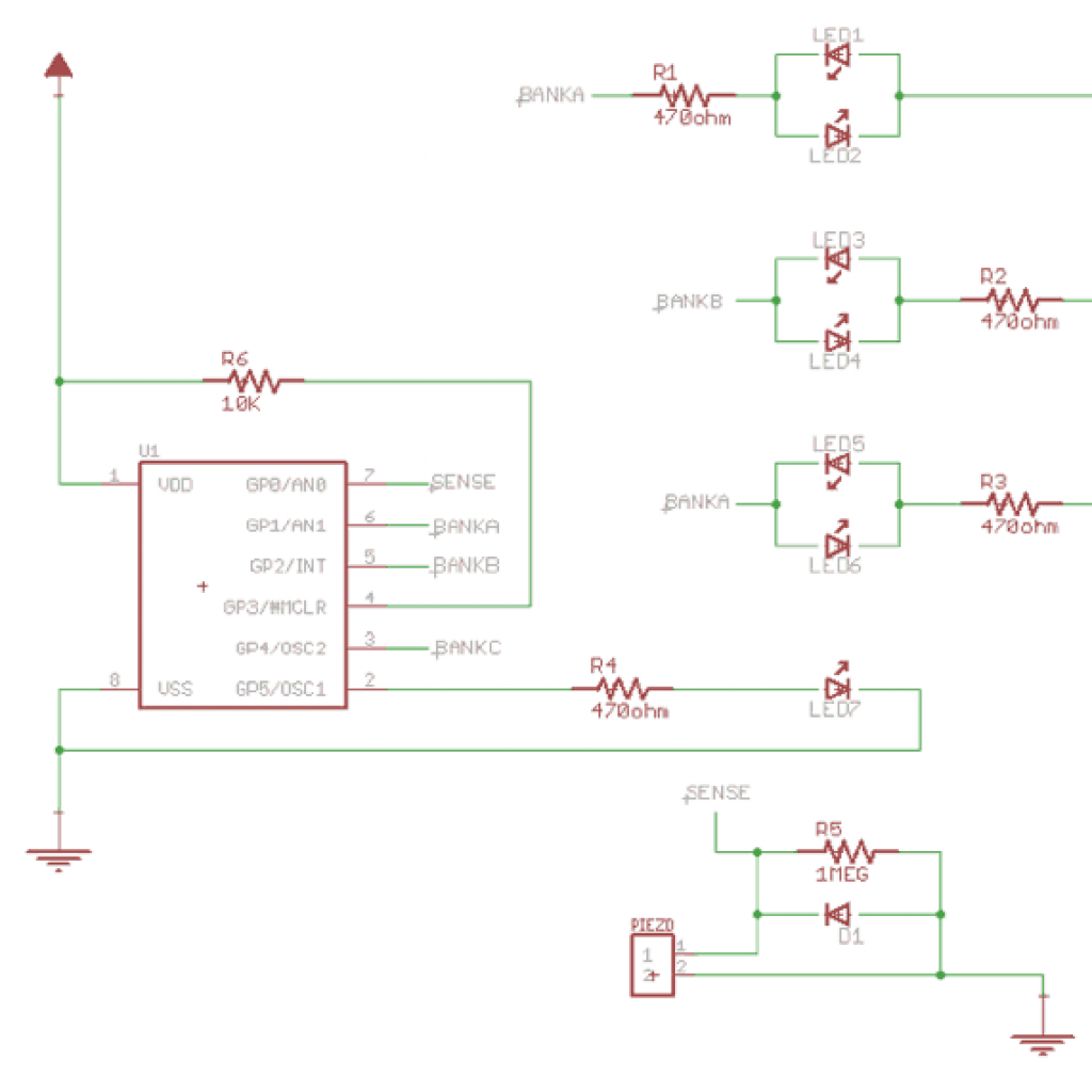
The electronic dice kit is made of 3 main components: the PIC microchip, the PCB and the Piezo impact sensor. Everything else in the dice kit is used for power or to help the main components communicate. The impact sensor sends an analog reading to the microchip, which runs it through a function to select a random number from 1-6. This number is then displayed by the LED’s on the top of the PCB.
In-Depth overview
To start the die, you need to apply a small amount of force to the acrylic base by tapping it onto a hard surface. The force of said impact will cause the Piezo sensor on the bottom to take a voltage reading and send it through a diode. The diode acts as a surge protector for the fragile microchip that does the actual processing of the data. The analog voltage reading is passed from the diode to the PIC microchip which then converts it to a decimal. From that decimal, it runs a function based off of the least significant decimal to retain the highest degree of randomness. The function will return a number from 1 to 6. This number is passed through a set of 6 resistors and their respective LED’s, lighting up when they are part of a pattern that corresponds to a number.