Design and Code
GitHub Repo:
https://github.com/parthanjaria123/Running-Glasses
Modification Milestone
For my modification milestone, I tried to map my route while running. My idea was that I would use a Python program to be able to receive the GPS coordinates from the Arduino and then use those coordinates to graph a map of my running route on Google Maps.
To execute this plan, I first used the Python Serial library to make it possible for my Python program to communicate with my Arduino Nano. Then, I identified the type of information sent to the program by using the type() function and casted the byte type to a float to be used by my program. Then, by using the gmplot package, I was able to use the Google Maps API to graph my route on my laptop whenever I was walking with my Arduino and GPS Module connected to my laptop.
However, after being able to carry out all this, I realized that I had looked over a crucial step during my planning. My nano ran on battery, and it would output information using the serial interface after I pressed a button. However, when I would take the nano off of battery to put it into my laptop (after which I would press a button and expect it to send the data to the Python program) I realized that as soon as the Nano was off power all the data would be lost. Hence, I ended up creating a car mode in which, as long as you had the device connected to your laptop, you could map your route while wearing the glasses. The route would show up your laptop screen after you pressed a button at the end of your ride.
During this milestone, I learnt how to incorporate Python with Arduino, how an Arduino actually transmits data, and how APIs work.
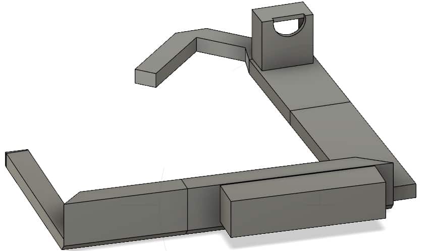
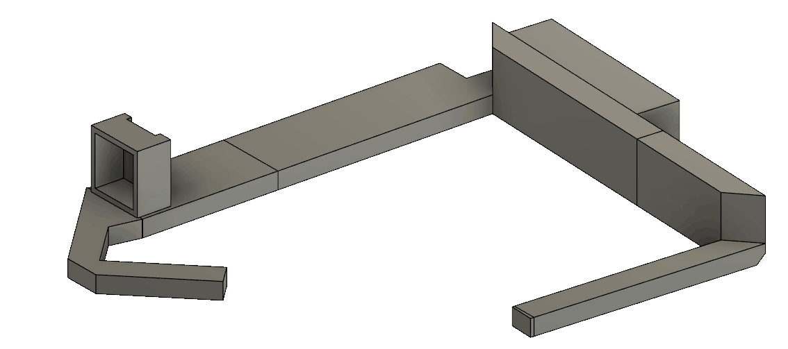
I’m looking forward to being able to CAD and 3D print my glasses!
Third and Final Milestone
For my third milestone I got the GPS (Global Positioning System) to work, and combined it with my OLED Display. GPS uses a process called trilateration to pinpoint your location on the Earth. In essence, trilateration is a process where at least three satellites create probability spheres of where you’re most likely to be located. The center of the intersection of these spheres is where it predicts you are, hence allowing it to provide a latitude, longitude, and altitude.
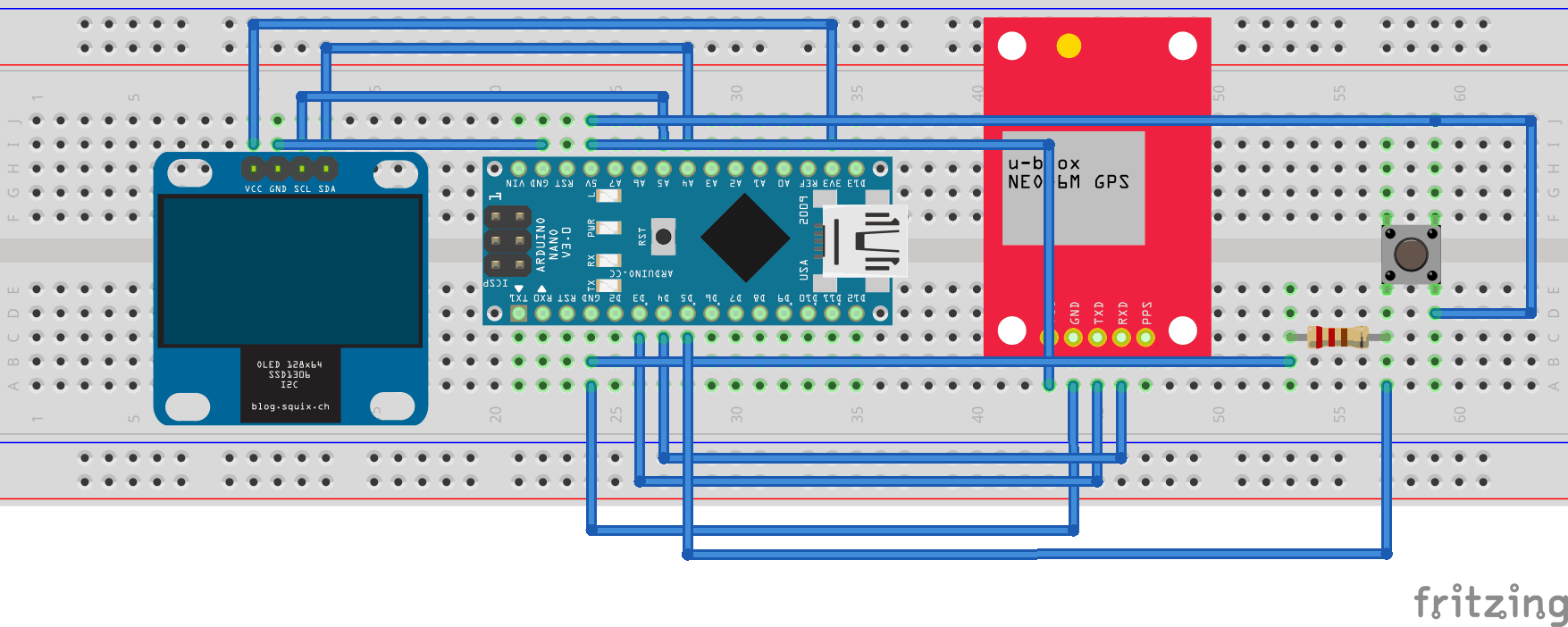
This information is then through radio waves to your GPS Module, which intercepts in the form of NMEA sentences. These sentences have a specific syntax that you can decode to obtain the data you need – for example, the information before the first comma tends to be the number of satellites connected to your GPS antenna. After learning the syntax, I used the TinyGPS++ library to be able to more easily and efficiently decode this information, which I could then manipulate to obtain the variables I wanted:
Pace: Calculated from velocity at any given point in time
Mileage: Summation of small intervals of distance using the distanceBetween() function provided by the library to determine the distance between a pair of latitudes and longitudes
ΔAltitude: Compared altitude to any point in time with the initial altitude.
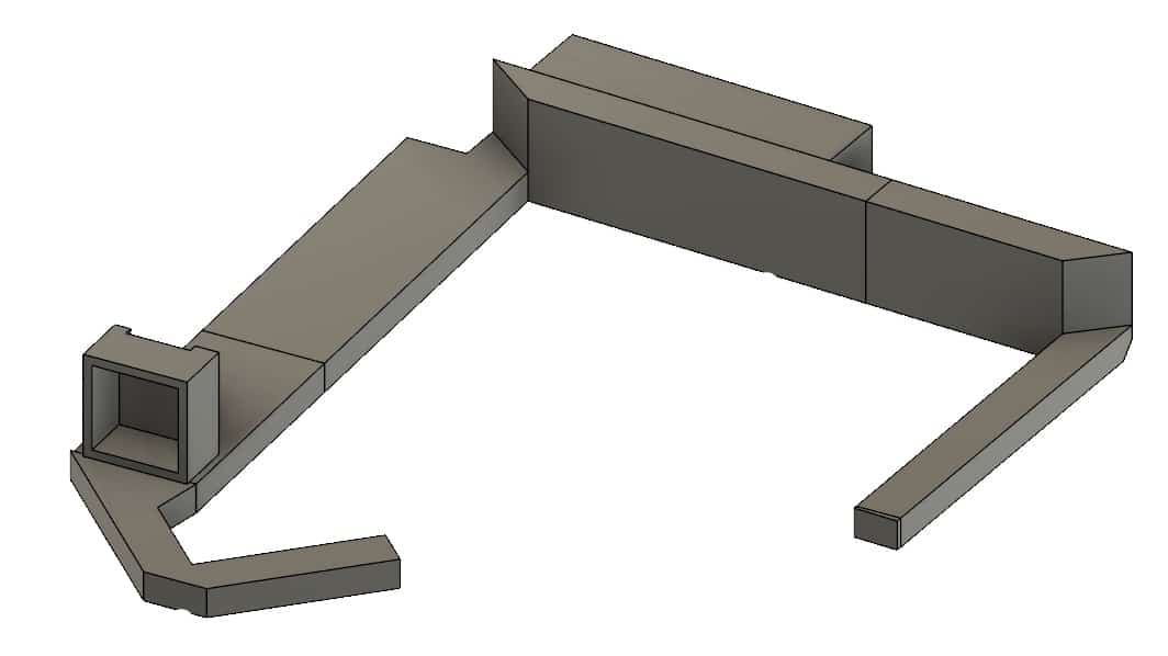
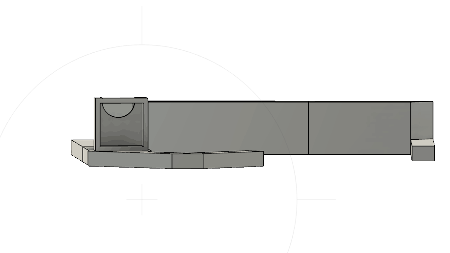
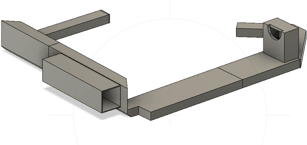
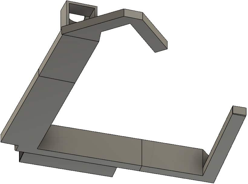
I created the frame for my prototype using cardboard. Using the law of reflection ( angle of incidence = angle of reflection), I was able to use mirrors and glass to reflect the light emitted by the OLED display back to my right eye.
When using the lens, I relied on the fundamental lens equation (1/di +1/do = 1/f) to create the focus where I wanted it on the glass and make the image clear and crisp.
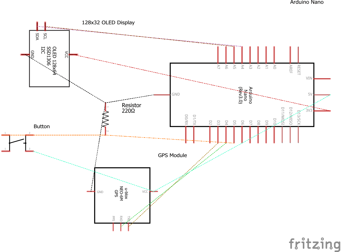
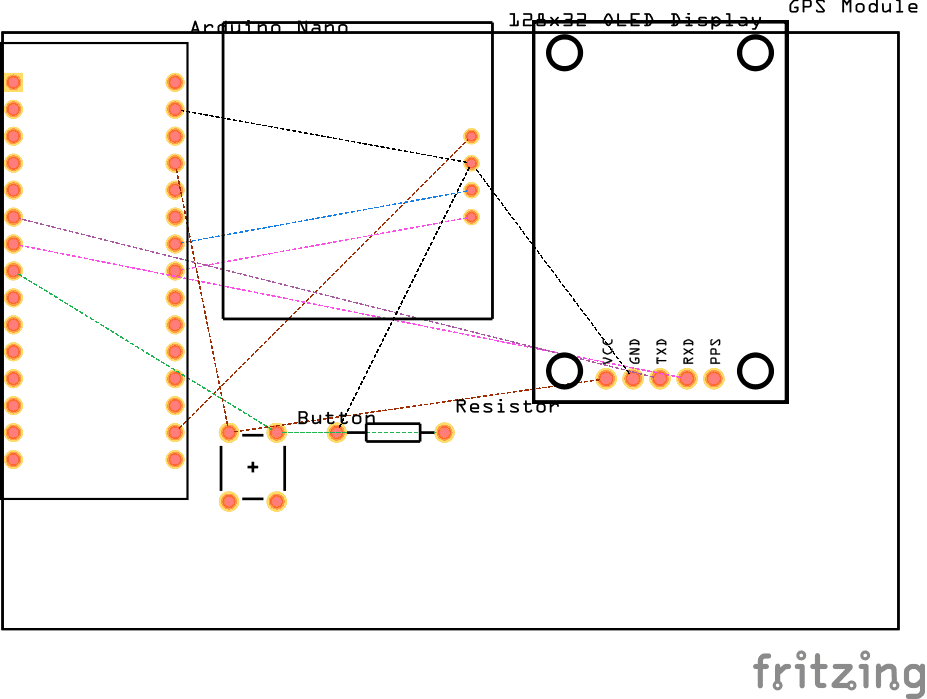
During this milestone, I learnt how to use a GPS module works, and, in more general terms, how most of the devices we use communicate with the satellites that create the Global Positioning System. Obviously, I also got to learn how to make a GPS module and an Arduino Nano communicate with each other – more specifically, how the ‘receive’ and ‘transmit’ pins work on both devices.
Now, I hope to be able to map my route using my GPS coordinates and a Google Maps API!
Second Milestone
My second milestone was getting my OLED Display to work. I got it to print the three main variables I wanted: Pace, Mileage, and Posture. In terms of how one works, an OLED Display has a few main components. The one closest to you is the screen, which allows all the components to stay inside and protects them. Then, in order, come the cathode, emissive layer, conductive layer, anode, and substrate. When electricity is run through the OLED, the cathode becomes negatively charged (contains a surplus of electrons) and the anode becomes positively charged (lacks electrons). Now, the anode has “holes”, or spaces in the anode that are missing an electron in them, and in order to neutralize them the conductive layer sends them towards the emissive layer, where the electron-filled spaces from the cathode meet the electron-lacking spaces from the anode. As these “holes” become neutralized, energy is released in the form of photons, or packets of light, which is what is emitted from the display. You can then further control the color of the light by adding colored filters.
For this project, I used an Adafruit library to allow me to use the OLED and send information and commands to it. I started off by setting each pixel on separately to print the letters I wanted on the screen, but soon realized that there was a built in print command that I later used.
For my next milestone I hope to get my GPS working and showing data on the OLED!
First Milestone
My first milestone was getting my accelerometer to work. To derive data from the accelerometer, I used a library with built-in functions to refer to certain values outputted by the accelerometer and an I2C bus to provide a physical route for the data to travel from the accelerometer to the Nano, which sent the information to my computer. Then to get velocity from the acceleration, I essentially used a trapezoidal Riemann sum. I took very small intervals of time (about 5 milliseconds) and took the acceleration values at both ends of the interval. I took the average of these values and then multiplied the average by the width of the interval to get the change in velocity over that interval. Essentially, I integrated the acceleration to get the velocity.
While completing the milestone, I learned how to use libraries for accelerometers, how accelerometers work, and how to wire a Nano. I also faced three main problems: finding a library that would provide me the data with the accuracy I wanted it to, figuring out why the accelerometer wasn’t communicating properly with the Nano, and figuring out a way to remove error from the accelerometer. I achieved the first one after going through four libraries, figuring out which one gave me the most relevant data. I learned that ease of use was inversely proportional to functionality, hence I ended up using one of the more complicated libraries. There was a quick fix to solving the communication problems. Instead of using a breadboard, I soldered the components together in an effort to make sure that the current was transmitted between the two devices. To attempt to remove error in the accelerometer, I et conditional statements that would remove values if they were too small to matter in the calculations. Since I was taking a Riemann sum, these small errors could eventually add up and create much larger errors, hence it was important to perform this step. Due to this, I might switch to the GPS but for now I’ll try to get rid of that error.
float axf = IMU.getAccelX_mss();
float ayf = IMU.getAccelY_mss();
axf-=0.72;//0.67
ayf-=1.13;

float avgaccx = (ax+axf)/2;
float avgaccy = (ay+ayf)/2;

if(avgaccx<0.10&&avgaccx>-0.10){
  avgaccx=0;
}
if(avgaccy<0.10&&avgaccy>-0.10){
  avgaccy=0;
}

float avgvelx = avgaccx*0.0005;
float avgvely = avgaccy*0.0005;

float change = sqrt(pow(avgvelx,2)+pow(avgvely,2));

if(avgaccx<0){
  velocity = velocity - change;
}

else{
velocity = velocity + change;
}

Serial.println(abs(2.23694*velocity));
Motion Alarm
Credits:
- https://randomnerdtutorials.com/guide-to-neo-6m-gps-module-with-arduino/
- https://www.instructables.com/id/Arduino-Data-Glasses-for-My-Multimeter/
- https://create.arduino.cc/projecthub/fanatic-series/gps-speedometer-using-arduino-pro-micro-0a8fde
- https://www.instructables.com/id/Arduino-GPS-Oled/


