Reflection
During these past few weeks at BlueStamp, I learned about the many different types of engineering and how work as an engineer is conducted. Initially, I was set on doing a project that involved computer science as I have experience with programming. However, that was not the case at BlueStamp. Rather than learning just computer science, I gained the full experience of engineering doing both programming and mechanical engineering. In addition, BlueStamp introduced me to engineering essentials like documentation. I learned that documentation can separate an engineer from a hobbyist as engineers need to document their work for future references. One of the hardest yet most helpful skill I learned was self teaching myself. Rather than asking the instructors for a clear answer, I had to find the answer myself which was frustrating but very rewarding at the end. I learned more about my project such as how the power works in a photon and how to write Arduino code from scratch. My experience at BlueStamp was truly an exciting one. Building the project while getting to know the instructors was one of the many great experiences here. Below is a video of a demonstration of my project.
Modification Prototype #1
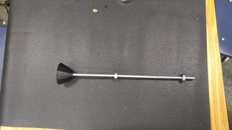
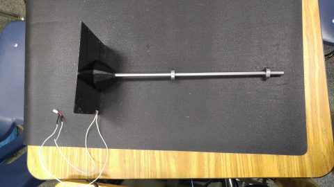
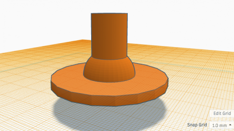
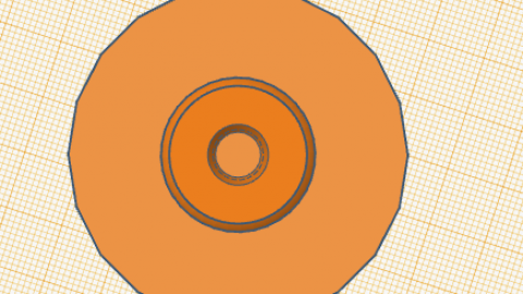
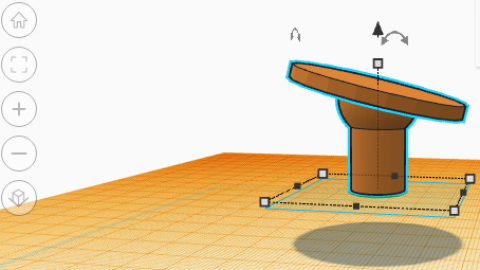
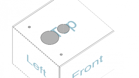
After prototyping for a few days, I have designed many components for my project such as the solar panel mount, the solar panel, and the enclosure. For my solar panel mount, I designed two different designs, one with a flat surface to connect to the solar panel and one with a tilted surface. The flat surface was obviously impractical as turning the solar panel would have no effect on the energy it receives from the sun, however, it was needed in order to understand how the solar panel would mount onto the axle. As a result, I changed the mount to be tilted in order to accommodate for the energy problem with the flat surface. According to this link, a 14 degree tilt would be best for the weather in California which is what I did. In addition to the solar mount, I also created an enclosure for my project which is made out of delrin. The design has four holes at the top, one for the axle, one for the cables, and two for the photoresistors. At the bottom, there will be one hole for the bearing for the axle. The solar panel mount prototypes, my enclosure, and a demonstration of my solar panel can be found below.
Milestone #2
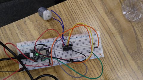
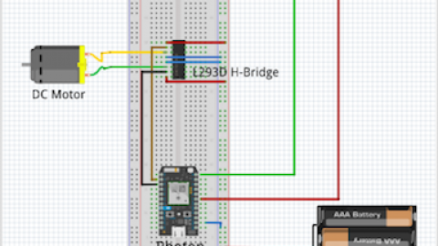
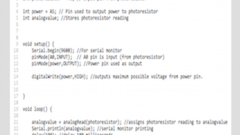
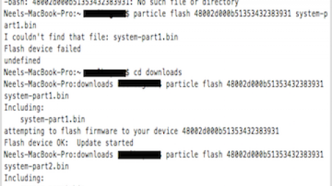
Today I completed the second milestone of my climate dashboard. What I have accomplished today is a great step towards the completion of my project. I have learned how to control the dc motor using the photo resistor that I connected to my photon. I faced many challenges when attempting to reach this goal such as bricking a photon and spending countless hours researching ways to achieve this. I found numerous solutions on how I can fix my photon, however, due to poor documentation, I was unable to understand how I can use the solution such as the one on this link and on this link. In addition, I tried flashing new firmware into my photon, however, it ended up leaving the photon in safe mode and ultimately making it useless. I found it was taking a lot of the time I needed for my project so we ordered a new unit allowing me to continue with my main project. After I received the new unit, I found that the only reason I couldn’t get accurate readings from the photo resistor was that I needed a resistor to limit the voltage going to the photo resistor according to this link. Once I found that was the issue, I got my motor up and running. During this step, I learned a whole lot about my project and some of the components in it. I learned how to read pin values from a photon and how to use pins as output values which I’ve been doing the whole time without realizing it. I also learned how to use an h-bridge to control the direction a motor can turn and how digital and analog pins can determine the behavior of the motor (with code). The code I wrote, my schematic, and some commands I used in the command prompt can be found below.
Milestone #1
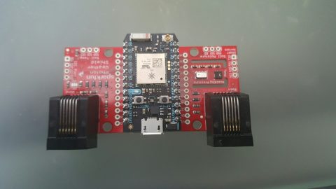
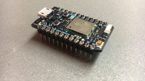
Today, I completed the first milestone for my climate control dashboard. During this step, I connected the hardware together and programmed the photon so that it can collect data.The two components I worked with were the photon microcontroller and the SparkFun Weather Shield. The photon microcontroller is a small computer chip that collects data from the sensors on the weather shield and reports it to the particle cloud. The code I used, allowed the Photon to collect readings from the Weather Shield sensors and to format it so that it could be read in the cloud. This was done by programming a web hook into the Photon so that the data it sends to the particle cloud is also sent to Losant. Because the Photon works by using wifi, I faced a challenge when connected the chip to wifi. It did not have a screen or anything to show if it was connected or connecting. Once I connected the chip to wifi, it worked great and reported all the data to Losant. The next steps to my project include creating a solar panel power supply as this is a weather station after all.
Main Project Resources
Bill Of Materials: https://docs.google.com/spreadsheets/d/1ZPr_gupiNAXtUB6mC1950pz_mWH62bccJ-PvNoYAVqE/edit?usp=sharing
Code: https://github.com/neelbagora/photoncode
Schematic: http://imgur.com/a/jNM2Z
Starter Project
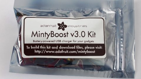
My starter project is the MintyBoost phone charger
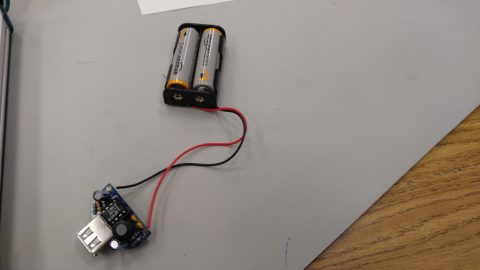
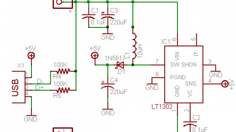
The MintyBoost is a phone charger that runs on 2 AA batteries. It works by converting battery power into sufficient energy to charge a cellular device. Building this project was a great experience with some challenges along the way. I learned so much as I was building this project, for example, I learned how to use a multimeter and how to use the continuity mode to test circuit connections. I also learned how to number an IC, how to read a schematic, and so much more. Towards the end when I finished my project, I found that it would not work. After some time spent troubleshooting, I found that one of the connections was not secure, interrupting the electrical current in the board. Upon fixing that, my MintyBoost became functional. By building this device, I learned a lot about circuitry, how to troubleshoot a circuit board, and how the components used in the project work. It was truly a great experience. Below, there is a YouTube video demonstrating the project and how it works.


Great job, Neel
Thanks!