
Hi! My name is Nathan and I am a rising senior at Ramaz. I was able to successfully build two separate projects, a starter project and a main project, during my six weeks at Bluestamp. For my starter project I began building the “voice modulator” however, the speaker didn’t work. So, I decided to build the TV-B-Gone instead. The TV-B-Gone is a relatively simple mechanism that uses infrared signals (the same as those used by TV remotes) in order to Turn a TV on an off. For my main project I chose to work on a robot that is controlled by a playstation 2 controller. I chose this project because I knew that I wanted a project that would incorporate both technical engineering and coding. Before Bluestamp, my experience in the field of engineering amounted to a couple of hours a month working with the Engineering club in my school. I had very little knowledge about even the basics such as soldering. During my time at Bluestamp I was able to amass a knowledge of Engineering that that included the names and functionality of basic engineering components (resistors, transistors, microprocessors, LED’s), how to code an arduino uno, how to solder properly, and most importantly, how to solve difficult problems.
My experience at Bluestamp was truly eye opening. Over the course of six weeks I was able to satiate some of my curiosity about the field of engineering by learning a great deal about the field. Simultaneously, through my experience I learned lasting life lessons. I learned that with the right amount of hard work, persistence, and drive, you can achieve anything. At first, it was a bit frustrating to work on something about which I had very little idea, but by the end of the six weeks I discovered a real love for engineering.
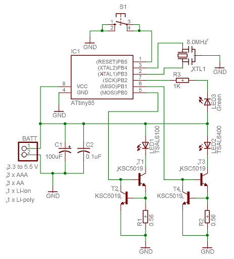
Schematics


Arduino code for ps2 controlled robot: CODE
Final Milestone
For my final milestone I was able to make a few significant changes to my project. The most significant change is in the functionality of the robot itself. The functionality of my Robot is now essentially flawless. I was able to add various new commands to my playstation controller to make it so that the robot could move in all directions. I modified my arduino code in order to command the controller to move the robot in directions other than simply forward and backward. This process was relatively difficult because I had to write code for each individual servo separately. The robot can now move forward, backward, forward and to the left, forward and to the right, backward and to the right, backward and to the left, turn right and turn left. The modification of the code was as follows: I plugged in the values of the joy stick at which I wanted the robot to move forward and to the left. At those particular values I programmed the controller to command the right servo to move at a first speed than the left. I did the opposite in order to move the robot forward and to the right. I did essentially the same thing in order to make the robot move backward in either direction, however I made it so that the servos would simply move in reverse. Next I added code that would allow the robot to turn right and left. The code was not particularly difficult to write. In order to make the robot move to the left, I made it so that, at the indicated joy stick values, the left servo would not move at all and the right servo would move at full speed.
In addition i was able to make physical modifications to the exterior of the robot. Using a 9 volt battery pack as a power source for my robot I made it so that the robot no longer needs to be hooked up to a computer in order to work. In other words, it is now wireless. This addition was extremely exciting. I’m now able to bring my robot anywhere without the constraints of having it being connected to my computer. Another modification i made was that I put black tape over the entire robot in order to make it a bit more aesthetically pleasing.
Difficulties: At this point in time I had very little difficulty. I am very familiar with all of the different aspects of my project.
Second Milestone
milestone #2 : connecting the robot to the wireless ps2 controller in order to control it.
For my second milestone I connected my robot to a wireless playstation 2 controller. I achieved this through connecting the wireless receiver of the controller to my arduino uno. I looked up a schematic diagram of the receiver itself, it revealed to me the purpose of each of the 9 ports on the receiver. The schematic also showed that only 7 of those ports were necessary when connecting it to an arduino. After everything was hooked up to the arduino I had to test the the controller to ensure that it was in working condition and that i had not made any errors while connecting the wires. The method I used for checking the PS2 controller was first downloading the PS2 controller library (can be found on the internet) and placing inside of my arduino libraries. I then “included” the library in my code and uploaded the code. After it was uploaded I opened serial monitor in order to test the controller and to make sure that each individual button was working. What the serial monitor does is it prints the name of each button as it is pressed so that you know that the receiver picked up what you are pressing. It prints values for the two joysticks as well.
After testing the controller’s functionality the next step was to program the PS2 controller to be able to command my servos. I began by finding simple code online that would command my servos to move forwards and backwards. The problem though, was that my servos are positioned in a way that makes it so that they go in opposite directions when commanded to do the same thing. Therefore, I had to modify the code in a way that would command the servos to go in opposite directions, effectively making them spin in the same direction. I didn’t want my robot to just be able to move forwards and backwards so I wrote code to make it so that the robot could turn right, turn left, move up and to the right, move up and to the left.
Difficulties: I had some difficulty with each individual step of this process. The first was the physical wiring of the receiver to the arduino. I had hooked up the wires to the arduino and tested it but it didn’t work at first. I tried rewiring it about five times and i couldn’t figure it out. It turns out that i had placed the receiver in the opposite direction it was supposed to be in so all of the wires were essentially in the wrong positions. I had minimal difficulty getting the PS2 controller connected to my servos because i found the code online. However coding the extra commands was pretty difficult. I had to erase and rewrite it a bunch of times.
First Milestone
Milestone #1:
Attaching servos + wheels to the base of the robot and programming the wheels to spin in the same direction simultaneously
I began this process by downloading the necessary program from the arduino website. Next I attached my first servo to the arduino. After that my next step was to find the arduino code necessary for it to communicate with the first servo and to tell it to move. After I was able to get the first servo moving (using arduino code) I had to figure out how to power two servos at once. This process was a bit more difficult than i had anticipated. I had to connect both of the servos to the arduino using a breadboard as the intermediary between the three. I didn’t have much difficulty connecting everything to the breadboard. However I did have significant difficulty figuring out how to program the arduino to command two servos simultaneously. At first i had difficulty getting them to move at the same time. Once I was able to get them to move at the same time they began moving in opposite directions. I then had to modify the code in such a way that the two servos would move simultaneously but in opposite directions.
Once I had programmed the two servos to work in sync my next step was to begin building the infrastructure of the robot. I cut out a rectangular piece of wood to use as the base of my robot. I drilled four holes into the base so that i could attach the servo mounts to the wood. I attached the mounts using screws, nuts, and washers. My next move was to attach the actual servos to the mounts. After finishing all of that I was finally able to attach wheels to each of the two servos.
Starter Project
Starter Project name: TV-B-Gone
Project description: A device that turns off nearly all televisions by sending a binary signal in the form of infrared light. The device works very similarly to a TV remote.
Project Process.
For my starter project I assembled the TV-B-Gone. The TV-B-Gone requires a lot of soldering and patience. An important factor to consider while working on this project is to make sure each individual piece is being put into the correct holes. If one piece is placed in the wrong holes the mechanism will most likely not work at all.
I began by soldering the resistors into their designated holes. I then soldered the capacitors and transistors. There are 5 transistors that must be soldered to the PCB. 4 of the transistors are essentially the same: therefore they can be placed in 4 spots arbitrarily. However there is one transistor that is different from the others and therefore it must be placed in a specific location. I almost made a mistake and soldered the one differing transistor into the wrong holes. My next step was soldering the 8 pinned microcontroller chip-holder. The purpose of the holder is to avoid having to solder the chip directly. The reason the chip cannot be soldered directly is because it is sensitive to heat and could break if soldered. Finally I soldered the LEDs. When soldering the LEDs you have to keep in mind that the LEDs must be bent over the PCB. The reason being that when the LEDs shine infrared light the light must be shined directly at the TVs receivers in order for the signal to be received.
I had little difficulty assembling this project. I had originally began with a different starter project however i could not get the first one to work for a variety of reasons. The experience with soldering that the first project gave me is what allowed this project to be as easy as it was.
Explanation of Individual parts:
PCB (printed circuit board): The circuit board is the vehicle through which all of the other pieces can come together and work in unison All of the various pieces are soldered to the PCB. The most important piece of the project.
Capacitors: used to store an electric charge in order to power elements of the circuit that need more power
Transistors: amplifies either sound or current. In the case of the TV-B-Gone the transistors amplify the current in order to power the LEDs
resistors: used in order to regulate current to prevent elements of the circuit from receiving too much current and frying
LEDs (Light Emitting Diode): The LEDs are what send the signal to the TV to shut off. The signals are in the form of infrared light. The Tv is able to read the signal because the infrared light is sent in the form of binary. This code is essentially the universal television code for turning off.
Microcontroller: the microcontroller is what has the program that tells the LED’s to shine in a certain way that signals the TV to shut offBattery pack: The battery pack is what powers the device itself.