Reflection
I had a solid plan all laid out when I first started working on my Third Eye for the Blind. I would follow the instructions I found online, finish my base project in only a couple days, then spend the rest of my time working on modifications. Instead, my base project required more thought than I expected and took much longer to program. After I had figured out the basics of electronics and finished deleting and rewriting half the code I found online, I could finally move on to modifications. My first thought was implementing a bluetooth module, but that would take more time than I had. I was disappointed, but I settled for what I thought was the next best thing- adding a GPS. It was actually my second modification that excited me the most. I designed my own PCB and held it in my hand. Unfortunately I had designed one of my Arduino headers backwards and wasn’t able to use it during my presentation. Despite that disappointment, designing my PCB sparked my interest in electrical engineering, a field I had previously thought of as boring and unsatisfying. That excitement made my entire project worth the six weeks of struggle.
Modification 2
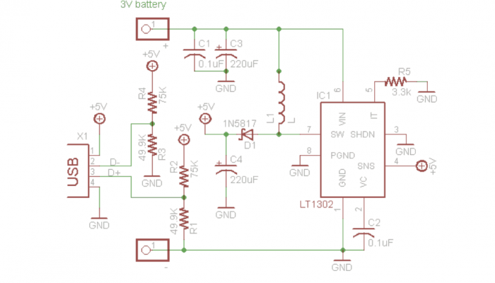
My second modification was by far the most enjoyable element of my project. I designed my own PCB using Autodesk Eagle and ordered it through OSH Park. The most difficult concept to grasp before I could make any real progress on my design was Eagle’s disregard of dimensions or position while designing a schematic. I spent a fair portion of time struggling to find dimension settings for my schematic before learning that the dimensions of parts only matter while designing the board. The most critical part of designing a schematic is confirming that the footprints on your schematic match the actual footprints of your parts. A footprint is the physical blueprint for each through hole you will be using to solder each part to your PCB. After I added the correct parts to my schematic, the next step was connecting each part with the correct wiring. After optimizing my wiring to include as few right angles as possible and the shortest routes possible, I generated my board in Eagle. Here was where dimensions and placement mattered. I measured the physical space my parts would require on the board and adjusted my design accordingly. After adding a silkscreen with my name and year, I ordered my PCB.
Modification 1
My first modification is the addition of a GPS tracker to my Third Eye design. I wanted to be able to track where the wearer of my Third Eye had been and view that information on my serial monitor. I soldered a GPS onto my perfboard and added the necessary code. Initially, finding the correct code and rewriting parts of it to integrate correctly with my existing Third Eye code was a tediously difficult process, but it became easier with time. After I managed to correctly add the right code, my GPS activated, but wouldn’t display on the serial monitor. After some lengthy online research, I realized my mistake was that I had been using the incorrect BAUD rate for my serial monitor. BAUD rate is how quickly information is transmitted through a channel of communication, and up until that point, I had been using a BAUD rate too high to receive data from the GPS. After correcting my code, my GPS was fully functional.


