Voice-Controlled Robot
My main project is a voice-controlled robot with edge-detecting capabilities. The robot can either follow vocal directions, or be controlled with an Android app. It runs with Arduino and uses a NodeMCU for a micro-controller.
Engineer
Nandini T.
Area of Interest
Computer Science
School
Saratoga High School
Grade
Rising Sophomore
Reflection
During these six weeks at BlueStamp I learned a great deal about engineering, as well as some basic life skills. At this camp I became more independent with my research techniques. Before I came, I would always ask a teacher or parent a question and get the answer given to me exactly as I wanted it. I never utilized the resources I had right in front of me. Thanks to this course, I have realized that Google actually does have all the answers; I just never tried to find them myself before.
Another thing I learned is what kind of engineering I am drawn to most. Earlier I only had exposure to the computer science aspect of engineering. I never worked on hardware or learned about circuit boards and micro-controllers. While working on my robot I had the opportunity to try out both software and hardware. To my surprise, I enjoyed hardware considerably more than I thought I would. However, even though I had a lot of fun creating circuits and sensors, I also realized that troubleshooting for physical components is much harder than debugging software. After spending weeks replacing fried micro-controllers and realizing an entire circuit didn’t work because of one loose wire, I learned that hardware is not for me.
Finally the biggest thing BlueStamp helped me with was my public speaking. I used to hate presenting in school because I got really nervous talking in front of an audience. Through the milestone videos and final presentation of my project, I greatly improved my confidence with presenting while having many people watching. This can really help me later in life with more projects and jobs.
All the code I used for this project is on GitHub
Materials I used for this project are in my Bill of Materials
Final Milestone
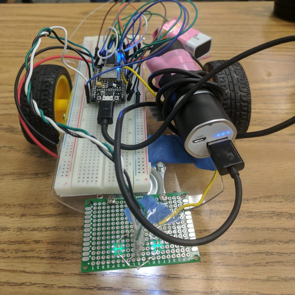
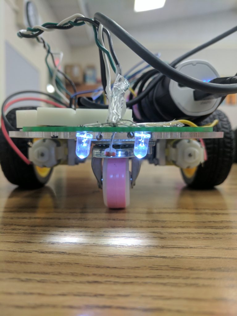
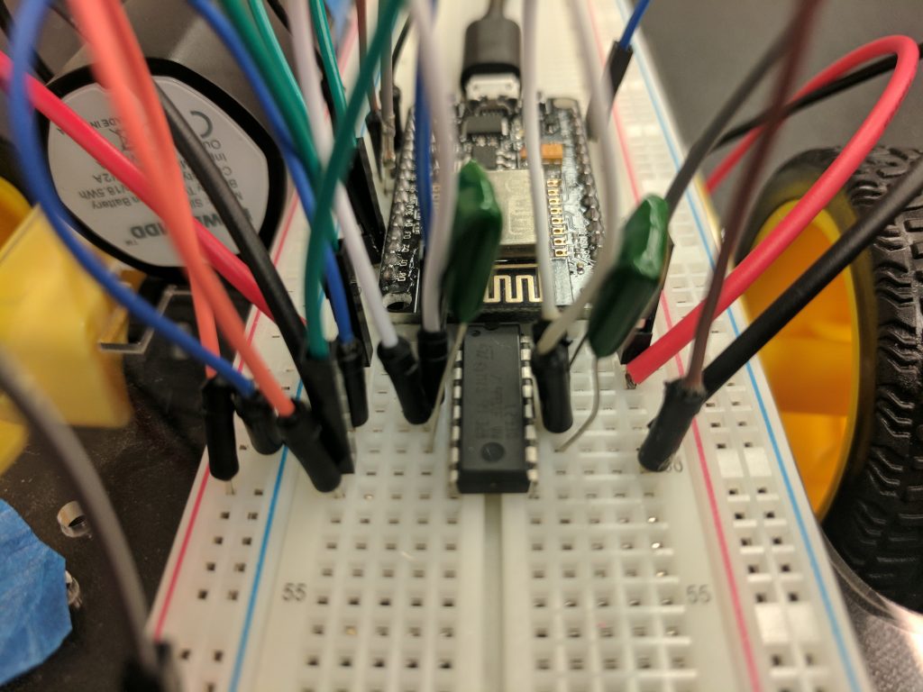
This is my final milestone. Since my last milestone I have added an edge detecting sensor that keeps the robot from falling off the edge of a table. I made the sensor myself using two LEDs, a photoresistor, and two resistors, which are soldered onto a PCB. I followed an online tutorial to make this sensor.
The edge sensor works because the photoresistor detects light that is emitted by the LEDs. When the sensor is above a table, more light is reflected back to the photoresistor, so the values that are read are higher. When the sensor is above the floor, less light is reflected and the values are lower. I implemented this into my code by saying that the robot should keep moving until it detects that the photoresistor is reading values below a certain level. I had a lot of problems with reading the values on the photoresistor.
At first I wasn’t able to both connect to wifi and read values. I tried many different iterations of the code to try and figure out what the problem was. Sometimes the photoresistor would send the wrong values, and other times the motors wouldn’t work. After a lot of research I realized that, if a sensor was being read to often, it would interfere with the WiFi connection of my micro-controller. I also had to replace my NodeMCU many times because it kept breaking.
Link to my code: Final code
Milestone #2
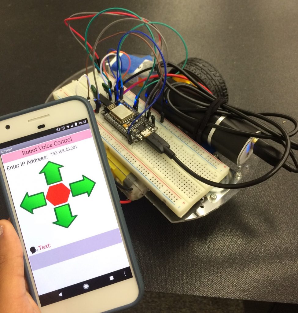
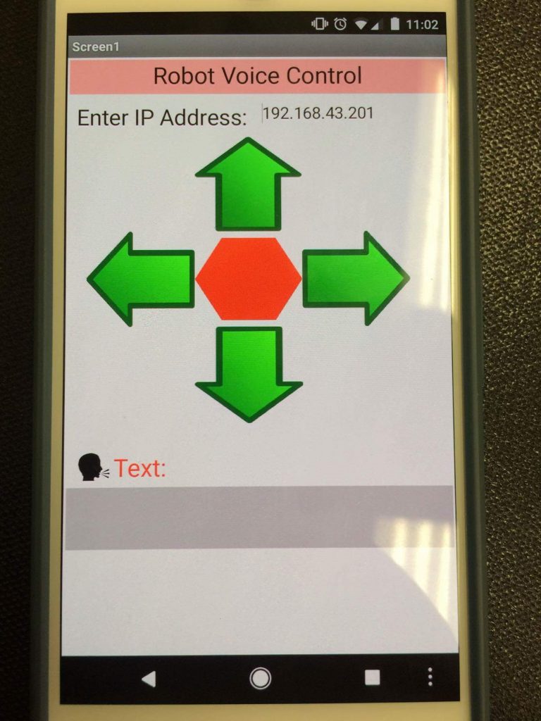
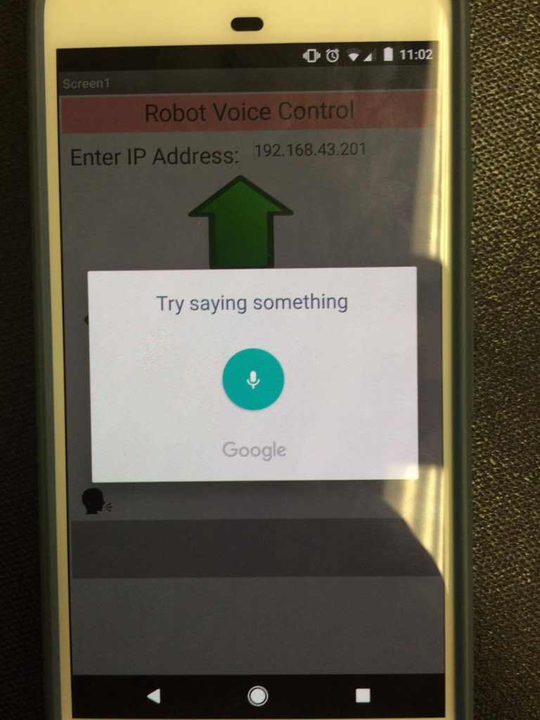
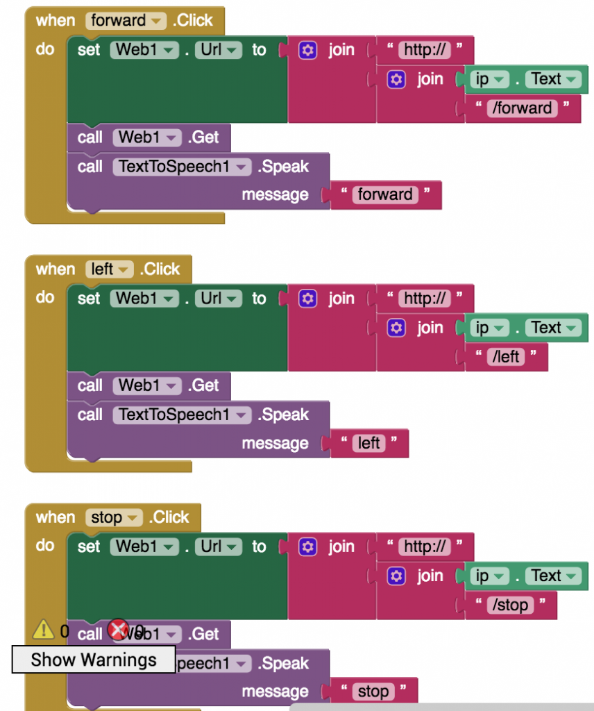
At my second milestone, everything is working as it should be. I can control the robot with buttons in an Android app as well as with voice in that app. I created the app using MIT App Inventor, where I designed the interface and then used blocks to code for the app. The code for the blocks came from an online tutorial.
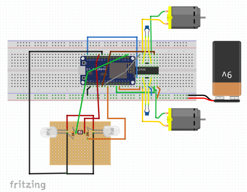
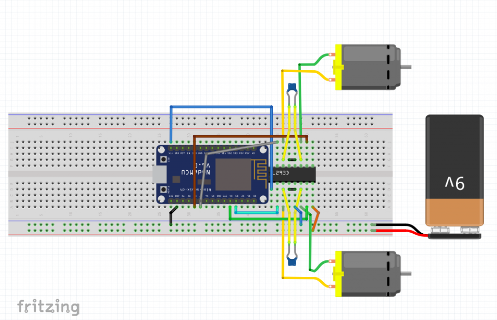
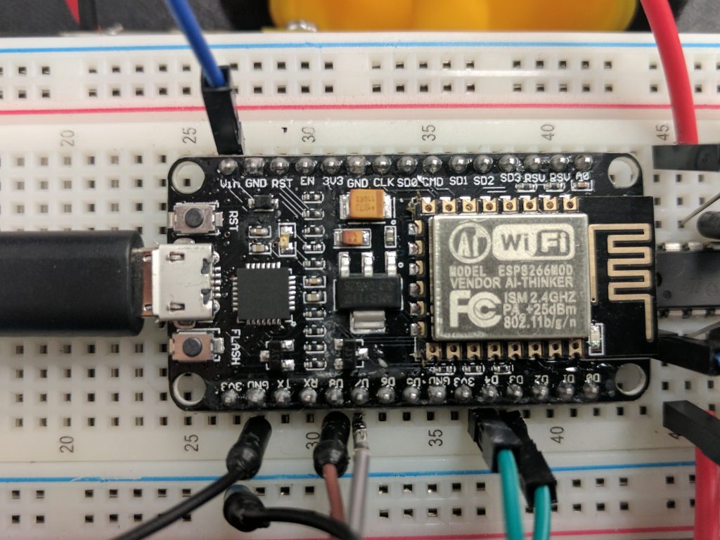
I have wires that connect the NodeMCU, my micro-controller, to the H-bridge motor driver’s input pins. This is how the NodeMCU tells the motor driver what to do. My wheels are connected to the motor driver’s output pins so that they can be controlled. Currently I am using a 5 volt battery pack to power the NodeMCU and a 9 volt battery to power the H-bridge. I had previously tried to use a boost converter, which can convert voltages. I was planning to take out my 9 volt battery completely and instead rely on the battery pack and boost converter to provide different voltages to each area. However, when I tried that everything stopped working. Even when I switched back to a 9 volt battery the wheels wouldn’t move, and the motor driver would get extremely hot. I had to replace it, after which everything worked like normal.
While working on this part of my project, I realized that the robot was moving too fast when turning to accurately move. After some research I realized I could substitute digitalWrite with analogWrite in my code. I tried giving values between 0 and 255, but later realized that this only worked with an Arduino. Since I was using a NodeMCU, I had to use the range of 0-1023 to make the motors move at different speeds. For my next step I plan to integrate sensors to keep the robot from falling off a table.
Here is a link for the code I used: Milestone 2 code
Milestone #1
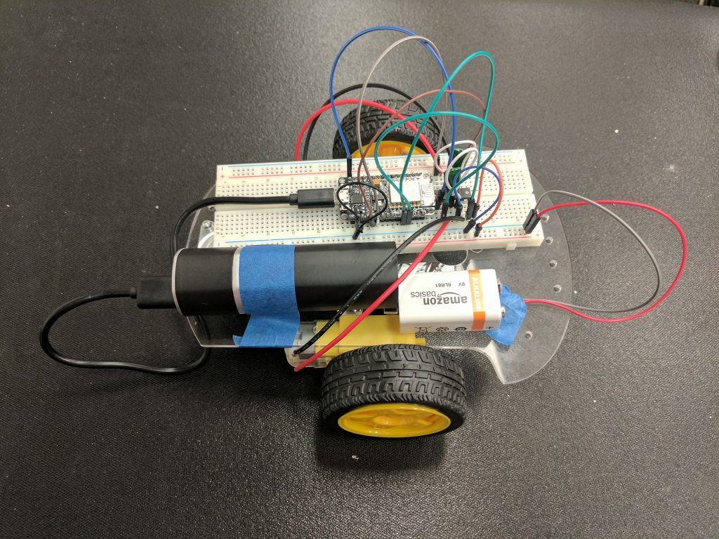
For my main project I am making a voice-controlled robot that will eventually be able to follow any directions it is given by a person’s voice. It will also be able to be controlled with an app. The robot uses a solderless breadboard with a NodeMCU and an L293D, as well as two DC motors, a 5 volt battery pack, and a 9 volt battery.
At milestone 1 I have been able to make the robot move forward, back, left, and right. I did all my wiring on a breadboard because it is a less permanent way to make connections. This means that any mistakes can be fixed by just unplugging a wire instead of going through a tedious desoldering process. I have two DC motors that are used for the wheels. This type of motor is simple to use and works perfectly with my project. The micro-controller I have is a NodeMCU, where I upload my code. The NodeMCU also has the ability to connect to WiFi, which I will use later when I connect the robot to a mobile app. I also have an L293D, which is an H-bridge. H-bridges are motor drivers, so they control my motors. I connected the wires from the motors to the output pins on the motor driver. The whole robot is powered by two separate batteries. The NodeMCU gets power from a 5 volt battery pack. The motor controller get power from a 9 volt battery, which ends up being the source of energy for the two motors.
This part of my project took some time because the diagram of the wiring that needed to be done was wrong. When I followed the instructions I was given on the project’s website, none of the motors moved. I ended up researching a different, simpler way to connect everything. I also removed some unnecessary parts of the code. In the end I was able to get both motors to move. My next step is to create an Android app and connect the NodeMCU to it using WiFi.
Link to test motors: Code for testing motors
Starter Project
Gram Piano
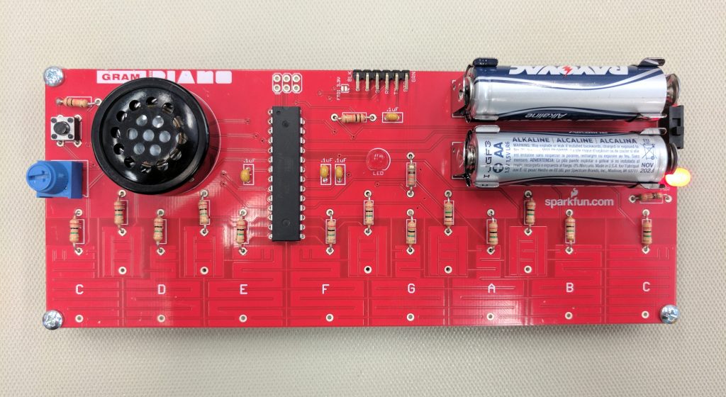
My Starter Project is a Gram Piano. The piano is a PCB (printed circuit board). Soldered to the PCB are a micro-controller, a potentiometer, LEDs, resistors, and capacitors. The piano runs on two 1.5 Volt batteries.
The Gram Piano functions as a regular piano which can play one octave at a time. However turning the potentiometer sends different values of resistance to the micro-controller, which can result in a total of three different octaves that can be played. Each time a key is pressed, the PCB uses capacitive touch to sense the press and send a signal to the micro-controller, which then sends a signal to the speaker to play the tone. There is also a button located on the piano which can play a pre-programmed melody.
I learned a lot while building this project. In the beginning I learned to solder for the first time. Further into the project I researched the function of every part on my piano. I learned that the micro-controller controls the entire piano, resistors reduce the amount of current, and capacitors store charge. I also learned that the PCB has a copper layer called the conductive track, which is how the current travels.